
Displacement sensor follower mechanism for testing the thickness of the oil film on the auxiliary shoe

A displacement sensor, oil film thickness technology, applied in the direction of instruments, measuring devices, etc., can solve the problems of data cable winding, complex sliding shoe movement state, and small sensor installation position, to achieve the effect of solving winding

Active Publication Date: 2016-09-07
ZHEJIANG UNIV
View PDF6 Cites 0 Cited by
  • Summary
  • Abstract
  • Description
  • Claims
  • Application Information

AI Technical Summary

Problems solved by technology

The motion state of the sliding shoe is relatively complicated. It not only has an elliptical revolution motion along the surface of the swash plate driven by the cylinder, but also has a spin motion around its own axis. In addition, the structure of the axial piston pump is very compact, so In the process of testing the relevant parameters of the shoe pair, there are two problems: the installation position of the sensor is narrow and the data line is entangled
Therefore, the relevant domestic and foreign test benches for testing the oil film thickness of the slipper pair have relatively large limitations: part of the test bench is a simulation structure with a swash plate rotating and a fixed cylinder block, which is completely related to the actual motion of the axial piston pump. On the contrary; the other part of the test bench is to limit the movement of the spin of the slide shoe through a mechanical limit
Therefore, although the design and processing of these test rigs are relatively simple and the test is convenient, these test rigs cannot truly simulate the actual dynamic state of the sliding shoe pair of the swash plate axial piston pump, so there are large errors in the test results of the oil film distribution characteristics

Method used


Image

  • Displacement sensor follower mechanism for testing the thickness of the oil film on the auxiliary shoe

Examples


Embodiment Construction

[0018] The present invention will be further described below in conjunction with accompanying drawing, with reference to accompanying drawing:

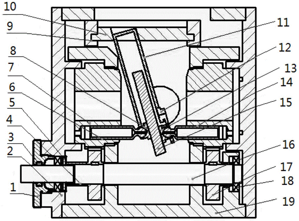
[0019] figure 1 Among them, 1 is the bearing end cover, 2 is the housing end cover, 3 is the felt ring, 4 is the sleeve, 5 is the oil seal, 6 is the auxiliary test plunger, 7 is the auxiliary test cylinder, 8 is the auxiliary test slide shoe 9 is The first sliding bracket, 10 is the second sliding bracket, 11 is the support frame, 12 is the sensor mounting plate, 13 is the test shoe, 14 is the test shoe, 15 is the swash plate, 16 is the transmission shaft, 17 is the pinion, The 18th, bearing, 19 housings.

[0020] The displacement sensor follower mechanism for testing the thickness of the auxiliary oil film of the slide shoe includes a housing 19 and a housing end cover 2. The main shaft is arranged in the housing 19 through a bearing. The main shaft is provided with a pinion 17 for input power and a pinion for output power. left an...


PUM


Abstract

The follower mechanism of the displacement sensor for testing the thickness of the oil film on the pair of slide shoes includes a housing and an end cover of the housing. The main shaft is set in the housing through bearings. The main shaft is equipped with a pinion for input power, a left gear and a right gear for output power. ;The plunger hole of the cylinder body is provided with a test plunger and a return spring; the axis lines of the test plunger and the auxiliary test plunger are on the same straight line, and the test slide shoe and the auxiliary test slide shoe are respectively attached to the two sides of the swash plate ; The swash plate is installed on the housing through a semicircular bearing; the support frame is slidably installed in the chute on the vertically slidable sliding bracket, and the support frame is sleeved on the outside of the swash plate; the sensor Both the mounting plate and the auxiliary test shoe are fixed to the support frame. The invention can continuously measure the thickness of the auxiliary oil film of the sliding shoe under the condition of simulating the real motion state of the sliding shoe of the swash plate type axial plunger pump.

Description

technical field [0001] The invention relates to a follower mechanism for continuous measurement of the oil film thickness of a sliding shoe pair of a swash plate type axial plunger pump, and is especially suitable for a test mechanism in which a test object has revolution motion. Background technique [0002] Due to the advantages of high power density and other advantages, axial piston pumps are widely used in industrial machinery and mobile machinery and other fields. And with the society's emphasis on energy saving and emission reduction, the efficiency and life of axial piston pumps have become a hot research topic for scholars at home and abroad. The three major friction pairs of the axial piston pump are one of the main factors determining its life and efficiency. Research shows that the energy loss of the sliding shoe pair is the first among the three friction pairs, and the oil film thickness of the sliding shoe pair is the key parameter to determine its leakage los...

Claims


Application Information

Patent Timeline
Patent Type & Authority Patents(China)
IPC IPC(8): G01B21/08
Inventor 徐兵王倩囡张军辉孙营辉葛耀峥
Owner ZHEJIANG UNIV
Learn More