


Quick Research
Generate reliable direction feasibility study reports for your R&D in just a few steps.

Technical Q&A
Discover and master advanced knowledge NOW. Basics, ideas, possibilities, all at once.

Find Solutions
As an expert in R&D theories, this can generate solutions to your technical problems instantly.

Evaluate Feasibility
Analyze your overall solution with one click, know your potential R&D risks in advance.

Monitor Landscape
Get weekly tech updates, stay abreast of the latest tech innovations and key insights.
Head anesthesia fixator for child
A fixator and head technology, applied in the field of children's head anesthesia fixer, can solve the problems of inconvenient operation, low efficiency, inconvenience for doctors, etc., and achieve the effects of smooth anesthesia process, avoiding resistance consciousness and improving reliability
- Summary
- Abstract
- Description
- Claims
- Application Information
AI Technical Summary
Problems solved by technology
Method used
Image

Examples
Embodiment 1
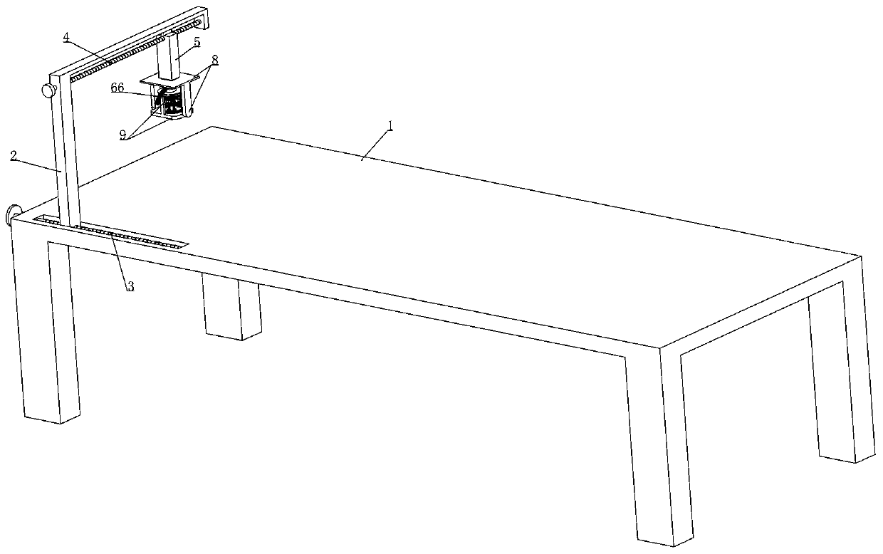
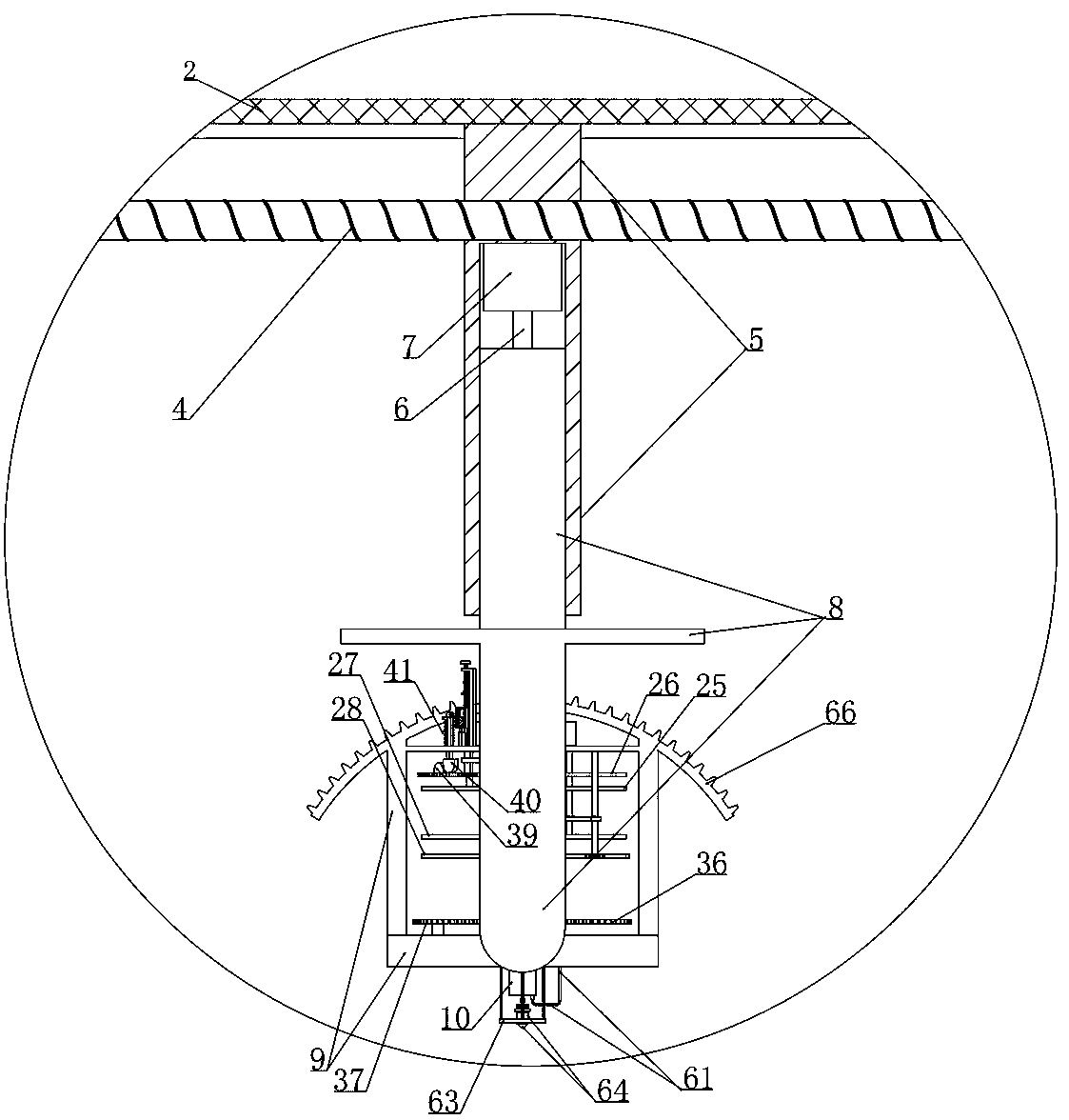
[0039] Embodiment 1, this embodiment provides a child head anesthesia fixator, refer to the attached figure 1 As shown, including bed platform 1, it is characterized in that, described bed platform 1 transverse one end is provided with laterally moving unit, and described laterally moving unit comprises the L-shaped frame 2 that lateral sliding is installed on the bed platform 1 and we rotate horizontal wire The bar 3 further controls the lateral movement of the L-shaped frame 2 on the bed platform 1. The longitudinal movement unit includes a longitudinal lead screw 4 that is rotatably mounted on the horizontal part of the L-shaped frame 2. The horizontal part of the L-shaped frame 2 is longitudinally slidably installed with The bearing cylinder 5 that is threadedly matched with the longitudinal lead screw 4, the bearing frame 8 is vertically slidably installed in the bearing cylinder 5, and the lower end of the bearing frame 8 is longitudinally rotated with a support plate 9 i...
Embodiment 2
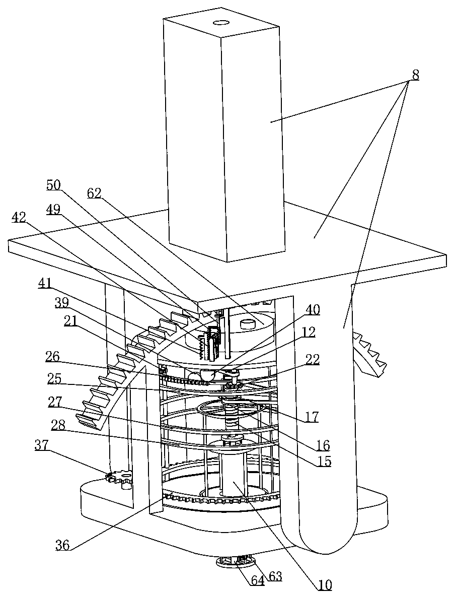
[0045] Embodiment 2, on the basis of embodiment 1, with reference to appended Figure 12 As shown, we put the inherent propulsion gear 21 on the propulsion shaft 18 and the inherent withdrawal gear 22 on the withdrawal shaft 14, the inherent injection gear 23 on the injection shaft 13 and the inherent extraction gear 24 on the extraction shaft 19, so The injection gear 23, withdrawal gear 22, push gear 21, and pull-out gear 24 are set at vertical intervals, referring to the attached Figure 8 As shown, the interval driving device includes an annular injection device, an annular withdrawal device, an annular propulsion device, an annular pull-out gear, which are respectively matched with the injection gear 23, the withdrawal gear 22, the pusher gear 21, and the pull-out gear 24 and are fixedly connected to the coaxial center. Out device, since the injection gear 23, the withdrawal gear 22, the advancing gear 21, and the extraction gear 24 are arranged at vertical intervals, so ...
Embodiment 3
[0047] Embodiment 3, on the basis of embodiment 2, with reference to appended Figure 8 As shown, the annular injection device, the annular withdrawal device, the annular propulsion device, and the annular extraction device include an injection ring 25, an exit ring 26, a pusher ring 27, an extraction ring 28 and a plurality of concentrically arranged injection rings. The fixed connection between the rings, refer to the attached Figure 11 As shown, an annular ring gear 36 that is rotatably mounted on the upper end surface of the supporting plate 9 and rotates coaxially with the plurality of annular rings is located at the position below the multiple rings. The transmission gear 37 on the support plate 9 and the propulsion motor 20 drive the annular ring gear 36 to rotate through the transmission gear 37, thereby realizing the effect of driving a plurality of said rings to rotate;
[0048] Refer to attached Figure 9As shown, we are fixed with some advancing gear trains 31 c...
PUM
 Abstract
Description
Claims
Application Information
 - R&D Engineer
- R&D Manager
- IP Professional
- Industry Leading Data Capabilities
- Powerful AI technology
- Patent DNA Extraction
Browse by: Latest US Patents, China's latest patents, Technical Efficacy Thesaurus, Application Domain, Technology Topic, Popular Technical Reports.
© 2024 PatSnap. All rights reserved.Legal|Privacy policy|Modern Slavery Act Transparency Statement|Sitemap|About US| Contact US: help@patsnap.com