A set of reinforced anti-torsion interlocking intramedullary nails

An intramedullary nailing and interlocking technology is applied in the field of reinforced torsion-resistant interlocking intramedullary nail kits, which can solve the problem that the location and type of femoral shaft fractures are not subdivided, the screws at both ends of the fracture site are far apart, and the local mechanical environment is inconsistent. It is beneficial to active osteogenesis, enhance anti-rotation ability, and improve the local mechanical environment.

Active Publication Date: 2021-06-08
林凤飞
View PDF7 Cites 0 Cited by
  • Summary
  • Abstract
  • Description
  • Claims
  • Application Information

AI Technical Summary

Problems solved by technology

The traditional interlocking intramedullary nail fixation method with this structure has the following disadvantages: the specific location and type of femoral shaft fractures are not subdivided, and all static fixation is used across the board, resulting in relatively concentrated stress around the fracture site and fractures. The screws at both ends of the site are far away, the local mechanical environment is not good, and the anti-rotation ability is poor, which is not conducive to fracture healing

Method used


Image

  • A set of reinforced anti-torsion interlocking intramedullary nails
  • A set of reinforced anti-torsion interlocking intramedullary nails
  • A set of reinforced anti-torsion interlocking intramedullary nails

Examples


Embodiment 1

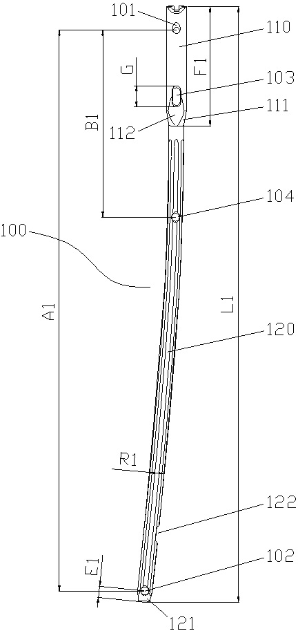
[0026] Embodiment one: if Figure 1~6 As shown, the present embodiment provides a reinforced anti-torsion interlocking intramedullary nail set, including:

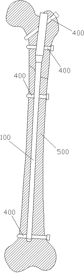
[0027] The first intramedullary nail 100 is used to fix the upper 1 / 3 fracture of the femoral shaft 500; the first intramedullary nail 100 includes a first shaft section 110 and a first shaft section 120 distributed sequentially from near to far, so The proximal part of the first rod head section 110 is provided with a first most end static locking hole 101, and the distal part of the first shaft section 120 is provided with a first most distal static locking hole 102; There is also a first proximal power locking hole 103 on the first shaft section 110, the first proximal dynamic locking hole 103 is located at the distal end of the first shaft section 110, and the first shaft section 120 is also provided with There is a first distal static locking hole 104, and the center distance B1 between the first most proximal static...

Embodiment 2

[0039] Example 2: Please refer to Figure 1~6 , The difference between this embodiment and Embodiment 1 is that: the reinforced anti-torsion interlocking intramedullary nail set further includes at least four screws 400, and the screws 400 are matched with corresponding locking holes.


PUM


Abstract

The invention discloses a reinforced torsion-resistant interlocking intramedullary nail set, which comprises a first intramedullary nail, a second intramedullary nail and a third intramedullary nail; the first intramedullary nail, the second intramedullary nail and the third intramedullary nail All intramedullary nails include a head section and a shaft section. The proximal end of the head section is provided with the most distal static locking hole, and the distal end of the shaft section is provided with the most distal static locking hole. The first intramedullary nail There is also a first proximal dynamic locking hole on the rod head section, a first distal static locking hole on the shaft section of the first intramedullary nail, and a second distal static locking hole on the shaft section of the second intramedullary nail. A proximal static locking hole and a second distal static locking hole, and a third proximal static locking hole and a third distal dynamic locking hole are provided on the shaft section of the third intramedullary nail. The invention adjusts the stress distribution around the fracture site by changing the distribution position and type of the locking holes of the intramedullary nail, improves the local mechanical environment, and enhances the anti-rotation ability of the intramedullary nail on the basis of maintaining the axial stability of the intramedullary nail.

Description

technical field [0001] The invention belongs to the technical field of medical devices, and in particular relates to a set of reinforced anti-torsion interlocking intramedullary nails. Background technique [0002] The femur is the longest tubular bone in the human body, and the femoral shaft includes the backbone from 2 to 5 cm below the tuberosity to 2 to 5 cm above the femoral condyle. When the femoral shaft is fractured, interlocking intramedullary nails are currently used for fixation. The proximal end and the distal end of the interlocking intramedullary nail are respectively provided with static locking screw holes, and the proximal end and the most distal end of the femoral shaft are respectively fixed by interlocking screws. remote. The traditional interlocking intramedullary nail fixation method with this structure has the following disadvantages: the specific location and type of femoral shaft fractures are not subdivided, and all static fixation is used across t...

Claims


Application Information

Patent Timeline
Patent Type & Authority Patents(China)
IPC IPC(8): A61B17/72A61B17/76
CPCA61B17/725A61B17/744A61B2017/564
Inventor 林凤飞
Owner 林凤飞
Why Eureka
Try Eureka