A High Refresh Rate Waveform Mapping Method and Digital Oscilloscope
A mapping method and refresh rate technology, applied in digital variable display, digital variable/waveform display, instruments, etc., can solve problems such as lower refresh rate, lower waveform refresh rate, and inability to process parallel waveforms in multiple columns
- Summary
- Abstract
- Description
- Claims
- Application Information
AI Technical Summary
Problems solved by technology
Method used
Image
Examples
Embodiment 1
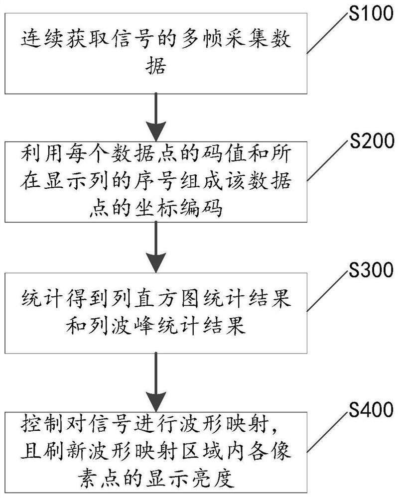
[0029] Please refer to figure 1 , the present application discloses a waveform mapping method with a high refresh rate. The waveform mapping method includes steps S100-S400, which will be described respectively below.
[0030] Step S100, continuously acquire multi-frame acquisition data of the signal, where each data point in the acquisition data is sequentially numbered according to the output order.
[0031] It should be noted that each data point in the collected data has a position number in the effective data stream, and the data point is output sequentially according to the position number. For example, in the effective data stream, the data number of the first clock is {L-1,L-2,..1,0}, the data sequence number of the second clock is {2L-1,2L-2,..L+1,L}, and the data sequence number of the third clock is {3L-1,3L-2,..2L+1,2L}, and so on, each data point can be marked. However, in this embodiment, each data point in each frame of collected data is sequentially numbered ...
Embodiment 2
[0057] Please refer to FIG. 6 , on the basis of the waveform mapping method disclosed in Embodiment 1, this application also discloses a digital oscilloscope 1 correspondingly, which includes a cache module 11 , an encoding module 12 , a statistics module 13 and a waveform display module 14 .
[0058] The buffer module 11 is used to continuously acquire multi-frame acquisition data of the signal, and buffer each frame of acquisition data, and each data point in each frame of acquisition data is sequentially numbered according to the output order. The buffer module 11 can be connected with a signal sampling component (such as an ADC conversion module) in the digital oscilloscope, and buffer the digitized data after sampling, interpolation or trigger position synchronization.
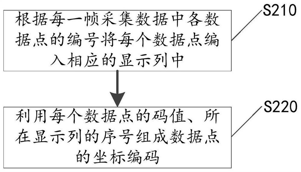
[0059] The coding module 12 is connected with the cache module 11, and is used to compile each data point into a corresponding display column according to the numbering of each data point in each frame of ...
PUM
 Abstract
Description
Claims
Application Information
 - R&D
- Intellectual Property
- Life Sciences
- Materials
- Tech Scout
- Unparalleled Data Quality
- Higher Quality Content
- 60% Fewer Hallucinations
Browse by: Latest US Patents, China's latest patents, Technical Efficacy Thesaurus, Application Domain, Technology Topic, Popular Technical Reports.
© 2025 PatSnap. All rights reserved.Legal|Privacy policy|Modern Slavery Act Transparency Statement|Sitemap|About US| Contact US: help@patsnap.com


