


Quick Research
Generate reliable direction feasibility study reports for your R&D in just a few steps.

Technical Q&A
Discover and master advanced knowledge NOW. Basics, ideas, possibilities, all at once.

Find Solutions
As an expert in R&D theories, this can generate solutions to your technical problems instantly.

Evaluate Feasibility
Analyze your overall solution with one click, know your potential R&D risks in advance.

Monitor Landscape
Get weekly tech updates, stay abreast of the latest tech innovations and key insights.
Air well patrol system
An inspection system and air shaft technology, applied in mining devices, manipulators, mining equipment, etc., can solve the problems of limited field of view, inaccurate evaluation, low efficiency, etc., and achieve the effect of convenient use and stable operation.
- Summary
- Abstract
- Description
- Claims
- Application Information
AI Technical Summary
Problems solved by technology
Method used
Image


Examples
Embodiment 1
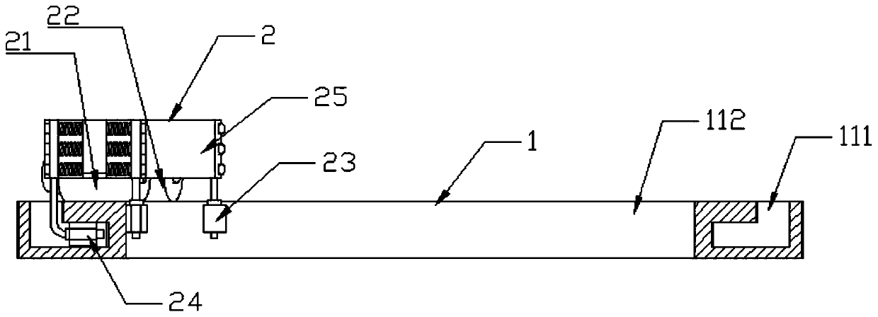
[0028] Embodiment 1, a wind well inspection system, such as figure 1 , 2 , 3 and 4, including:
[0029] The horizontal circumferential traction mechanism includes two parallel and vertically arranged annular guide rails 1, the guide rails 1 are fixed to the inner wall of the wind shaft through a number of trusses 11 evenly distributed around the sides; the two guide rails 11 are equipped with mobile trolleys 2 , are respectively the upper mobile trolley and the lower mobile trolley, two groups of rollers are arranged under the mobile trolley 2, one group is the driving wheel 21, and is connected with a motor through the reduction box, and the other group is the driven wheel 22.
[0030] The upper surface of the guide rail 11 is provided with an L-shaped guide groove 111 downwards, and the inner sidewall of the guide rail 11 is a guide surface 112; the mobile trolley 2 is provided with two guide wheels, which are respectively a longitudinal guide wheel 23 and a transverse guid...
Embodiment 2
[0036] Embodiment two, such as Figure 5 As shown, the top of the upper guide rail 1 and the bottom of the lower guide rail 1 are equipped with a rotary platform 71 through the truss 7, and the ground traction device 31 and the underground traction device 31 are installed on the two rotary platforms 71 respectively.
[0037] Specific implementation instructions:
[0038] This embodiment provides another way to install the traction device 31 . The two traction devices 31 are respectively installed on the two rotary platforms 71 , so that the traction devices 31 can follow the movement of the moving trolley 2 and rotate in a direction, thereby ensuring the stability of the inspection robot 4 . This embodiment aims to provide users with another convenient installation method in different scenarios and environments.
Embodiment 3
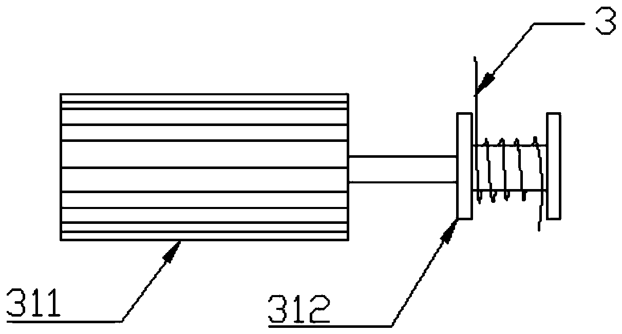
[0039] Embodiment three, such as Figure 6 As shown, the ground traction device in this embodiment can be arranged on the ground other than the air shaft, and the underground traction device can be arranged at the bottom of the air shaft, but this will cause the steel wire rope 3 to be unable to move with the mobile trolley 2 when the traction motor 311 is stationary. synchronous rotation. For this reason, the traction motor 311 can be set to run synchronously following the movement of the mobile trolley 2 through the control module, thereby changing the length of the steel wire rope 3 between the traction motor 311 and the mobile trolley 2, so that the traction motor 311 can move away from the traction motor 311 when the mobile trolley 2 is away from the traction motor 311. 311 releases the steel wire rope 3 ; This has not only ensured the free movement of the mobile car 2, but also ensured that the height of the inspection robot remains unchanged. This embodiment aims to pro...
PUM
 Abstract
Description
Claims
Application Information
 - R&D Engineer
- R&D Manager
- IP Professional
- Industry Leading Data Capabilities
- Powerful AI technology
- Patent DNA Extraction
Browse by: Latest US Patents, China's latest patents, Technical Efficacy Thesaurus, Application Domain, Technology Topic, Popular Technical Reports.
© 2024 PatSnap. All rights reserved.Legal|Privacy policy|Modern Slavery Act Transparency Statement|Sitemap|About US| Contact US: help@patsnap.com