


Quick Research
Generate reliable direction feasibility study reports for your R&D in just a few steps.

Technical Q&A
Discover and master advanced knowledge NOW. Basics, ideas, possibilities, all at once.

Find Solutions
As an expert in R&D theories, this can generate solutions to your technical problems instantly.

Evaluate Feasibility
Analyze your overall solution with one click, know your potential R&D risks in advance.

Monitor Landscape
Get weekly tech updates, stay abreast of the latest tech innovations and key insights.
LED interactive display screen easy to adjust
A technology of display screen and adjustment seat, which is applied in the direction of instruments, identification devices, supporting machines, etc., which can solve the problems of fixed display screen and inability to adjust conveniently, and achieve the effects of stable position, simple structure, and convenient trial use
- Summary
- Abstract
- Description
- Claims
- Application Information
AI Technical Summary
Problems solved by technology
Method used
Image

Examples
Embodiment 1
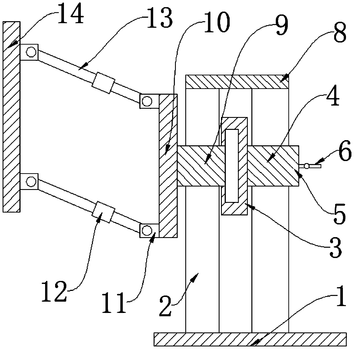
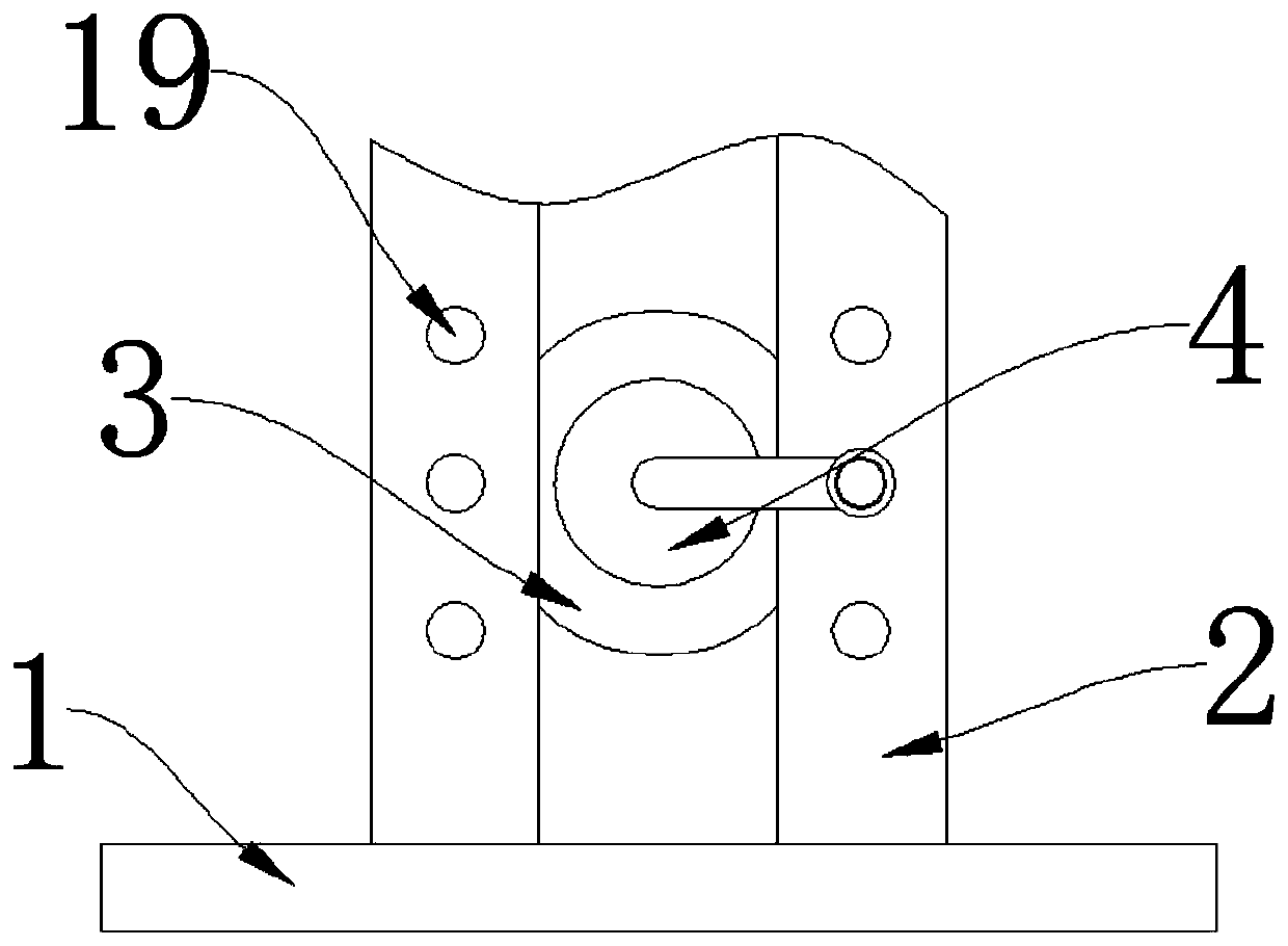
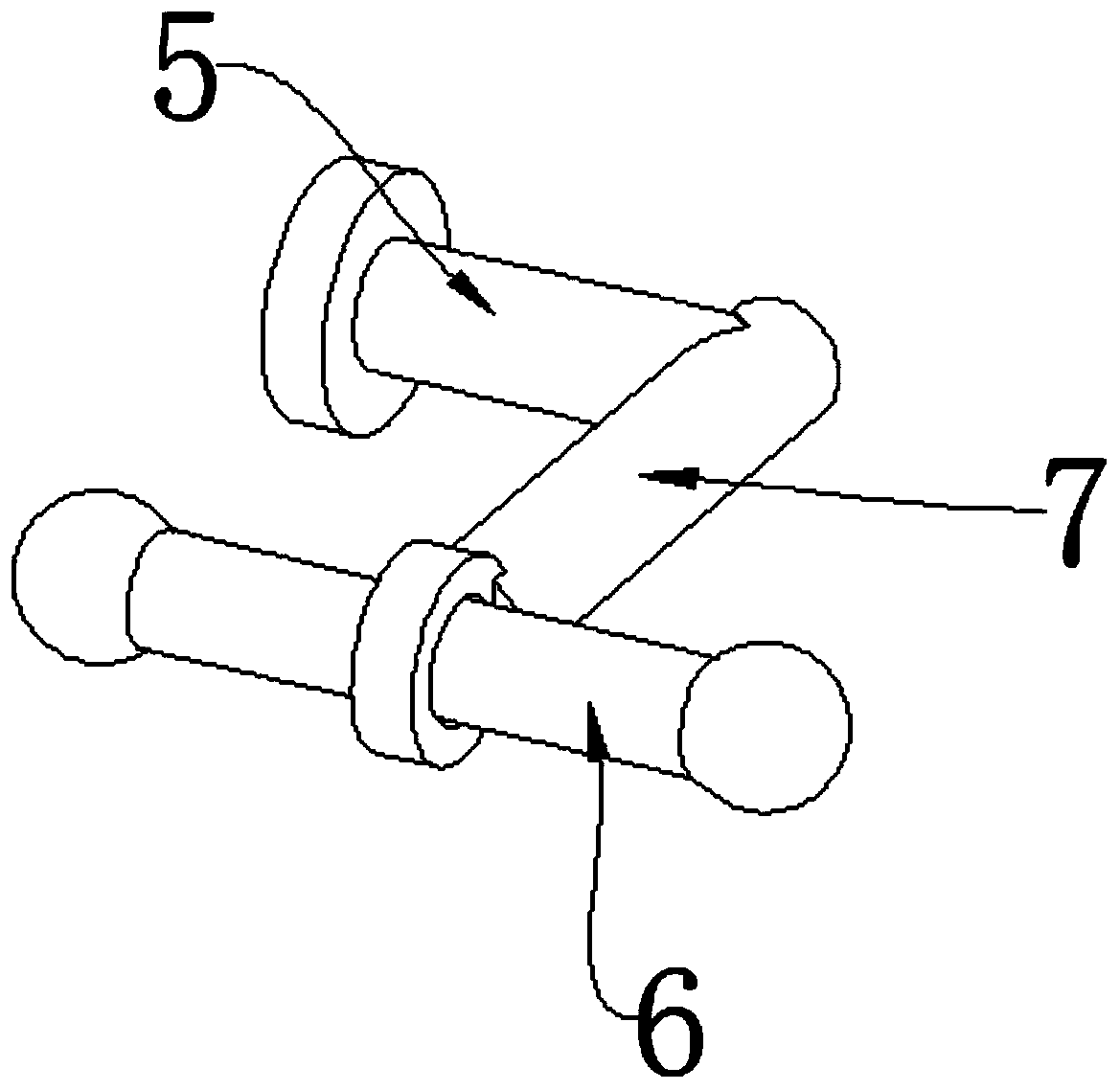
[0024] see Figure 1-4 , this embodiment provides an easy-to-adjust led interactive display screen, including a base 1 and a "П"-shaped adjustment seat 2, and there are two adjustment seats 2 that are relatively fixed on the base 1, and the two An adjustment groove is formed between the two adjustment seats 2, and a gear 3 is arranged in the adjustment groove, and a corresponding transmission tooth is arranged on the inner side of one of the adjustment seats 2, and several positioning gears are arranged on the outer side of the adjustment seat 2. hole 19, the side of the gear 3 is provided with a rotating shaft 4, and the end of the rotating shaft 4 away from the gear 3 is provided with a rotating handle, and the rotating handle includes a vertical bar 5, a horizontal bar 7 and a hand bar 6. One end of the rod 5 is fixedly connected to the rotating shaft 4, and the other end is connected to the cross bar 7, and the end of the cross bar 7 away from the vertical bar 5 is provide...
Embodiment 2
[0031] see Figure 5 and Image 6 On the basis of Embodiment 1, a driving mechanism for driving the rotating shaft 4 to rotate is also provided, the driving mechanism includes a power source 20 and a support rod 21, and one side of the power source 20 is drivingly connected to the rotating shaft 4, The other side is provided with a traction ring, the support rod 21 is in the shape of “┕” and one end thereof is fixedly connected to the base 1 , and the other end is located in the traction ring as a limiting structure of the power source 20 . The power source 20 is a micro motor. Driving the rotating shaft 4 to rotate through the power source 20 saves labor.
Embodiment 3
[0033] see Figure 7 , on the basis of embodiment 1, the connecting column 17 is provided with a number of fixing holes, the swivel 15 is provided with a through hole, and the fixing nail 18 is arranged in the through hole, so that at the height of the display screen 14 After the angle adjustment is completed, the relative position between the support rod 13 and the hinge seat 11 can be fixed, so that the position of the display screen 14 is more stable.
PUM
 Abstract
Description
Claims
Application Information
 - R&D Engineer
- R&D Manager
- IP Professional
- Industry Leading Data Capabilities
- Powerful AI technology
- Patent DNA Extraction
Browse by: Latest US Patents, China's latest patents, Technical Efficacy Thesaurus, Application Domain, Technology Topic, Popular Technical Reports.
© 2024 PatSnap. All rights reserved.Legal|Privacy policy|Modern Slavery Act Transparency Statement|Sitemap|About US| Contact US: help@patsnap.com