Screw vacuum pump temperature control device
A technology of temperature control device and vacuum pump, which is applied to parts of pumping device for elastic fluid, pump, rotary piston type/swing piston type pump parts, etc., can solve the difficulty of installation and maintenance, increase cost, The speed of disassembly and installation is stable, the speed of disassembly and installation is fast, and the effect of overheating shutdown is avoided.
- Summary
- Abstract
- Description
- Claims
- Application Information
AI Technical Summary
Problems solved by technology
Method used
Image
Examples
Embodiment 1
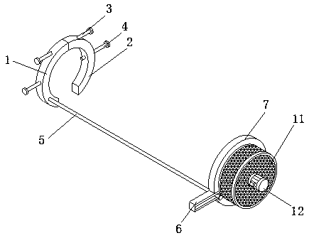
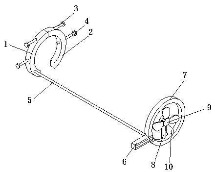
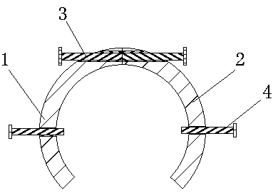
[0043] Example 1: Please refer to Figure 1-4 , a screw-type vacuum pump temperature control device, comprising a left fixed ring 1, a right fixed ring 2 and a cooling ring 7, the left fixed ring 1 and the right fixed ring 2 are fan-shaped, the concave surfaces of the left fixed ring 1 and the right fixed ring 2 Corresponding left and right, left fixed ring 1 and right fixed ring 2 have threaded holes on the top side of the side, and the screw holes on the top of left fixed ring 1 and right fixed ring 2 are in the opposite direction, and the threads on the top of left fixed ring 1 and right fixed ring 2 The hole is threaded on both sides of the outer wall of a double-ended screw rod 3. First, the double-ended screw rod 3 is turned to make the distance between the left fixed ring 1 and the right fixed ring 2 longer, and then the inner walls of the left fixed ring 1 and the right fixed ring 2 are aligned with The outer wall of the end of the vacuum pump away from the motor corre...
Embodiment 2
[0045] Embodiment 2: Please refer to the fixed ring 5-8 on the left in the figure. On the basis of Embodiment 1, an annular groove 14 is provided on the back side of the cooling ring 7. The annular groove 14 is an annular groove, and a slider is sleeved in the annular groove 14 B15, the material of the slider B15 is a magnet and is adsorbed in the ring groove 14. The back side of the slider B15 is provided with a word protrusion 16, and the outer wall of the word protrusion 16 is sleeved with a board 17, and the shape of the board 17 is The fan-shaped body, the front of the plug board 17 is provided with a slot 18, the slot 18 is in the shape of a line and is socketed with the protrusion 16 of the line, at first, according to the installation environment of the vacuum pump and the device, a certain number of Slider B15, then on the slider B15, insert the board 17 through the socket of the in-line protrusion 16 and the slot 18, and make the concave surface of the board 17 corres...
Embodiment 3
[0048] Embodiment 3: Please refer to the left fixing ring 9-16 in the figure. On the basis of Embodiment 2, the top surface of the insert plate 17 is provided with mounting holes 41 on both sides of the air outlet 21, and the inner wall of the mounting hole 41 is fixedly connected with Liquid-filled bag 42, liquid-filled bag 42 is a hollow ellipsoid and made of silica gel material, the top surface of cooling ring 7 is fixedly connected with liquid inlet box 22, the top surface of liquid inlet box 22 is hollowed out, and liquid inlet box 22 Sixteen liquid inlet ports 25 are fixedly connected to the back side of the body, and the liquid inlet ports 25 communicate with the inside of the liquid inlet tank 22. The nozzles of the liquid inlet ports 25 are fixedly equipped with pipe covers, and the liquid filling bag 42 is close to one end of the liquid inlet tank 22. The top surface is fixedly connected and communicated with a liquid pipe 27. First, fill the liquid coolant in the liq...
PUM
 Abstract
Description
Claims
Application Information
 - R&D Engineer
- R&D Manager
- IP Professional
- Industry Leading Data Capabilities
- Powerful AI technology
- Patent DNA Extraction
Browse by: Latest US Patents, China's latest patents, Technical Efficacy Thesaurus, Application Domain, Technology Topic, Popular Technical Reports.
© 2024 PatSnap. All rights reserved.Legal|Privacy policy|Modern Slavery Act Transparency Statement|Sitemap|About US| Contact US: help@patsnap.com


