
Slow-release resistance-increasing yielding anchor rod and method

It is a technology of letting the pressure bolt and slowing release. It is used in the installation of bolts, earth-moving drilling, construction, etc., which can solve the problems that are not conducive to the stability of the overall structure and the impact disturbance of the bolt-rock mass complex.

Active Publication Date: 2020-08-07
SHANDONG UNIV
View PDF6 Cites 2 Cited by
  • Summary
  • Abstract
  • Description
  • Claims
  • Application Information

AI Technical Summary

Problems solved by technology

Due to the instantaneous release of the energy accumulated by the deformation of the bolt during the shearing process, the limit bolt will cause impact and disturbance to the bolt-rock complex, which is not conducive to the stability of the overall structure

Method used


Image

  • Slow-release resistance-increasing yielding anchor rod and method
  • Slow-release resistance-increasing yielding anchor rod and method

Examples


Embodiment 1

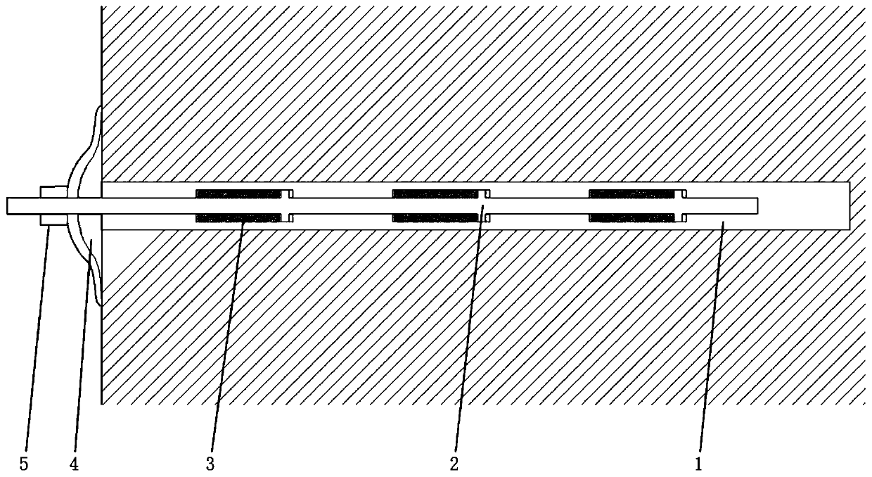
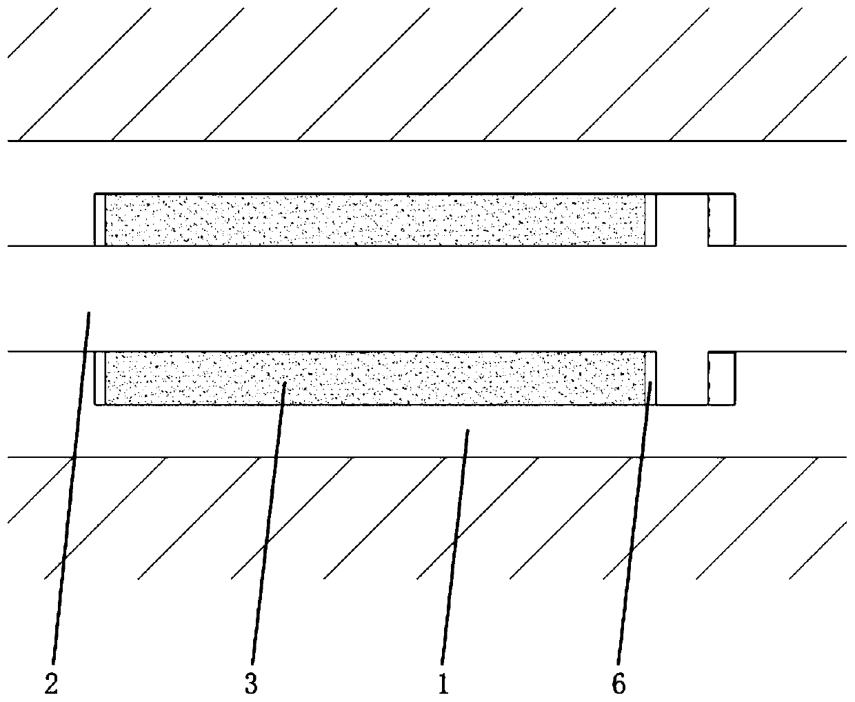
[0026] A slow-release, increasing resistance and yielding pressure anchor rod, comprising a sleeve 1, the sleeve 1 has an inner cavity along its own axis, one end of the sleeve 1 is blocked; the inner cavity of the sleeve 1 A shaft 2 is pierced, and one end of the shaft 2 extends into the inner cavity of the sleeve 1, and a connecting piece is installed at the other end, and the connecting piece is used for connecting the rock wall.

[0027] The inner cavity of the sleeve 1 is provided with a gas chamber 3, and the set position of the shaft 2 is provided with a piston, so that the gas chamber 3, the shaft 2, and the piston form a closed gas space; Compressed gas can be injected into the gas space, and the compressed gas is used to provide resistance when the shaft 2 slides away from the sleeve 1 . The piston can slide along the axial direction of the shaft 2 to realize the compression or expansion of the gas in the compression space.

[0028] In this embodiment, in order to r...

Embodiment 2

[0040] This embodiment provides a method for using a slow-release, increase-resistance, and pressure-releasing anchor rod, which includes the following steps:

[0041] Use commercial drilling equipment to drill holes on the surface of the rock and soil, the hole depth is consistent with the length of the sleeve 1, carefully clean the holes and install anchoring agent in the anchor holes;

[0042] Insert the rod structure consisting of sleeve 1, shaft 2, and rubber gasket 6 into the anchor hole, with the closed end of sleeve 1 facing into the hole, the open end of sleeve 1 flush with the surface of the rock and soil body, and the shaft 2 Part of the length is exposed outside the surface of rock and soil;

[0043] Set the anchor pad 4 on the exposed section of the shaft 2, with the raised side facing the outside of the rock and soil mass;

[0044] A bolt 5 is installed on the top of the shaft rod 2 and tightened, so that the anchor backing plate 4 is tightly pressed on the surf...


PUM


Abstract

The invention relates to a slow-release resistance-increasing yielding anchor rod and a method. The slow-release resistance-increasing yielding anchor rod comprises a sleeve, wherein an inner cavity in the axis direction of the sleeve is formed in the sleeve, and one end of the sleeve is blocked; a shaft rod penetrates through the inner cavity of the sleeve, one end of the shaft rod extends into the inner cavity of the sleeve, and a connecting piece is mounted at the other end of the shaft rod and used for being connected with a rock wall. A gas chamber is formed in the inner cavity of the sleeve, and a piston is arranged in a set position of the shaft rod, so that the gas chamber, the shaft rod and the piston define a closed gas space; and compressed gas can be injected into the gas spaceand used for providing resistance when the shaft rod slides in the direction away from the sleeve. The piston can slide in the axis direction of the shaft rod, so that compression or expansion of gasin the compressed space is realized.

Description

technical field [0001] The invention belongs to the technical field of civil engineering construction, and in particular relates to a slow-release, resistance-increasing, pressure-yielding bolt and a method. Background technique [0002] The 21st century is the century of underground space development and utilization. With the vigorous development of my country's transportation, energy, water conservancy and other infrastructure construction, underground engineering construction represented by tunnels, underground factories, and underground complexes has entered a period of rapid development. Soft rock is a common type of rock mass in engineering construction. Due to its large deformation and long deformation period, it often causes slippage or tensile failure of the anchorage structure. [0003] The inventor understands that the industry has developed various yielding bolt structures, but most of them use mechanical structures such as single or multiple limit pins to provid...

Claims


Application Information

Patent Timeline
IPC IPC(8): E21D21/00E21D20/00E02D5/74
CPCE02D5/74E21D20/003E21D21/0026E21D21/0033E21D21/0093
Inventor 李利平周申孙法合李术才刘洪亮王凯陈迪杨张延欢胡杰秦承帅
Owner SHANDONG UNIV
Learn More