Suspended dome structure suitable for square boundary and calculation method thereof

A chord-supported dome and boundary technology, which is applied to roofs, building components, building structures, etc., can solve the problems of difficult coordination of forces, unified and effective theoretical methods, and reduced structural efficiency of chord-supported domes, and achieves simple and convergent processes. Quick, easy-to-apply effects

Active Publication Date: 2020-08-07
ARCHITECTURAL DESIGN & RES INST OF SOUTHEAST UNIV CO LTD
View PDF6 Cites 2 Cited by
  • Summary
  • Abstract
  • Description
  • Claims
  • Application Information

AI Technical Summary

Problems solved by technology

In recent years, domestic suspend dome structures are mainly used in long-span space structures such as gymnasiums, conference halls, and exhibition halls. However, since the mechanical performance of suspend domes is closely related to the grid shape of the upper chord reticulated shell, it is unreasonable The grid form will greatly reduce the structural efficiency of the suspend dome
However, when the suspensive dome is applied to the square boundary, it is difficult to coordinate the force of the square boundary and the circular hoop cable, so it is very difficult to find the shape and force of the cable-strut shape and the upper chord reticulated shell. There is no unified and effective theoretical method, so the current application boundaries of suspend domes are mainly circular or quasi-elliptical boundaries

Method used


Image

  • Suspended dome structure suitable for square boundary and calculation method thereof
  • Suspended dome structure suitable for square boundary and calculation method thereof
  • Suspended dome structure suitable for square boundary and calculation method thereof

Examples


Embodiment Construction

[0022] The present invention will be further explained below in conjunction with the accompanying drawings and specific embodiments. It should be understood that the following specific embodiments are only used to illustrate the present invention and are not intended to limit the scope of the present invention.

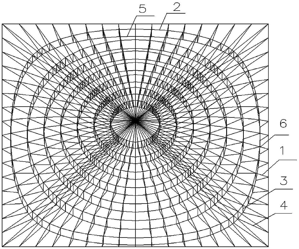
[0023] Such as figure 1 As shown, the present invention is a suspension dome suitable for a square boundary and its calculation method. The suspension dome includes an upper chord single-layer reticulated shell and a lower chord cable-strut system, and the upper chord single-layer reticulated shell includes radial rods 1 and circumferential rods 2. The lower chord cable rod system includes vertical struts 3, radial stay cables 4 (cable cables) and hoop stay cables 5 (ring cables). The central node of the upper chord single-layer reticulated shell is not provided with vertical struts, and the reticulated shell node 6 applies prestress to the cables through the tension ...


PUM


Abstract

The invention discloses a suspended dome structure suitable for a square boundary and a calculation method thereof. The suspended dome structure comprises an upper chord single-layer latticed shell and a lower chord cable rod structure, wherein the lower chord cable rod structure comprises a vertical supporting rod, a radial stay cable and an annular stay cable; an analysis process comprises the following steps of: solving a vertical load requirement and angles of the annular stay cable and the radial stay cable; generating a grid according to the angles of the annular stay cable and the radial stay cable; iterating a grid form; and calculating an annular stay cable pre-stress and the like. According to the suspended dome structure disclosed by the invention, on the basis of an initial form of a dome, an ideal vertical supporting rod supporting force is derived through an upper load, so that a new cable rod form and a corresponding upper chord grid form are derived; and the process isrepeatedly solved on the new form and the process is iterated for a plurality of times to obtain an ideal dome form. The suspended dome structure has the advantages that the blank that the suspended dome is adopted by the square boundary is filled and an explicit solution for generating an annular stay cable equal-internal-force suspended dome through correcting the angle of the annular stay cableis provided; and the stress performance of the suspended dome structure is ideal.

Description

technical field [0001] The invention relates to the field of architecture, in particular to a suspend dome structure suitable for a square boundary and a calculation method thereof. Background technique [0002] Suspension dome is a new type of spatial structure system that achieves force balance through the joint work of the upper chord single-layer reticulated shell and the lower chord cable-strut system. It has been theoretically researched and practiced in China for many years. In recent years, domestic suspend dome structures are mainly used in large-span space structures such as gymnasiums, conference halls, and exhibition halls. However, since the mechanical performance of suspend domes is closely related to the grid shape of the upper chord reticulated shell, it is unreasonable The grid form will greatly reduce the structural efficiency of the suspend dome. However, when the suspensive dome is applied to a square boundary, it is difficult to coordinate the force of ...

Claims


Application Information

Patent Timeline
Patent Type & Authority Applications(China)
IPC IPC(8): E04B7/14G06F30/13G06F119/14
CPCE04B7/14G06F30/13G06F2119/14
Inventor 韩重庆王国承
Owner ARCHITECTURAL DESIGN & RES INST OF SOUTHEAST UNIV CO LTD
Why Eureka
Try Eureka