
Unmanned ship for floating oil cleaning and recycling

A technology of unmanned ships and oil slicks, which can be used in the cleaning of special-purpose ships, unmanned surface ships, and open water surfaces. The effect of replacing and improving work efficiency

Inactive Publication Date: 2020-08-07
广州市欧伊若科技有限公司
View PDF0 Cites 1 Cited by
  • Summary
  • Abstract
  • Description
  • Claims
  • Application Information

AI Technical Summary

Problems solved by technology

[0002] The oil slick recovery device is a device for cleaning and recovering the oil slick on the water surface. Ships and industrial production will produce oily sewage leakage and discharge, causing oil pollution on the water surface, not only polluting ships, docks, beaches and other infrastructure, It is also easy to cause fire, especially the oil film destroys the circulation of oxygen, seriously damages aquatic resources, and brings great harmful effects to the human living environment. At present, two methods of recovery and dissipation are generally used to clean up oil slicks. For large areas Generally, oil-absorbing felts are used for the recovery of oil slicks for adsorption and recovery. When oil-absorbing felts are used for oil slick treatment, the oil-absorbing felts need to be replaced frequently, which is time-consuming and laborious, which affects cleaning efficiency, and the operator’s contact with oil slicks will affect their health. The oil-absorbing felt can be reused after cleaning, but the existing oil-absorbing felt degreasing device is generally carried out offline, which is troublesome to handle

Method used


Image

  • Unmanned ship for floating oil cleaning and recycling
  • Unmanned ship for floating oil cleaning and recycling
  • Unmanned ship for floating oil cleaning and recycling

Examples


Embodiment Construction

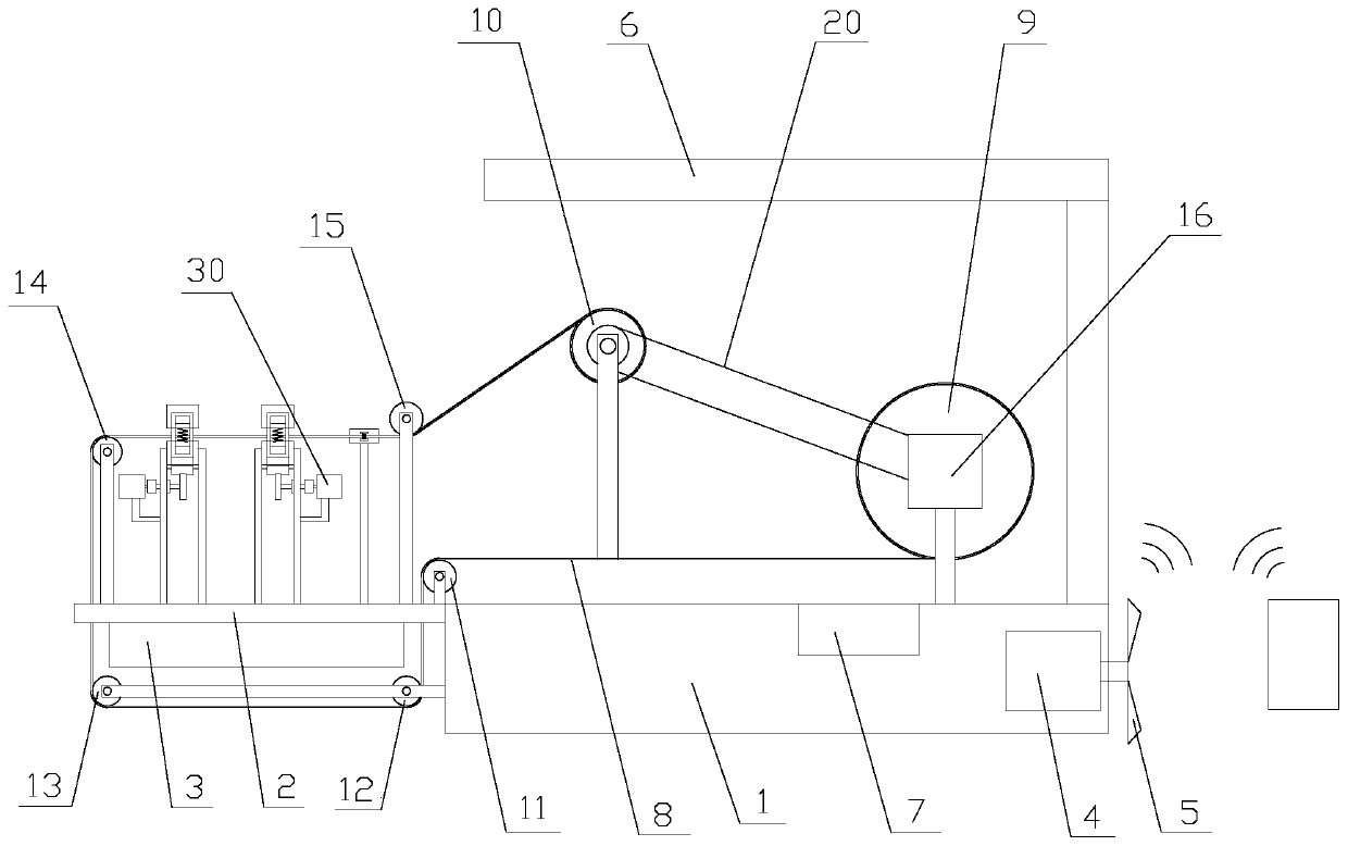
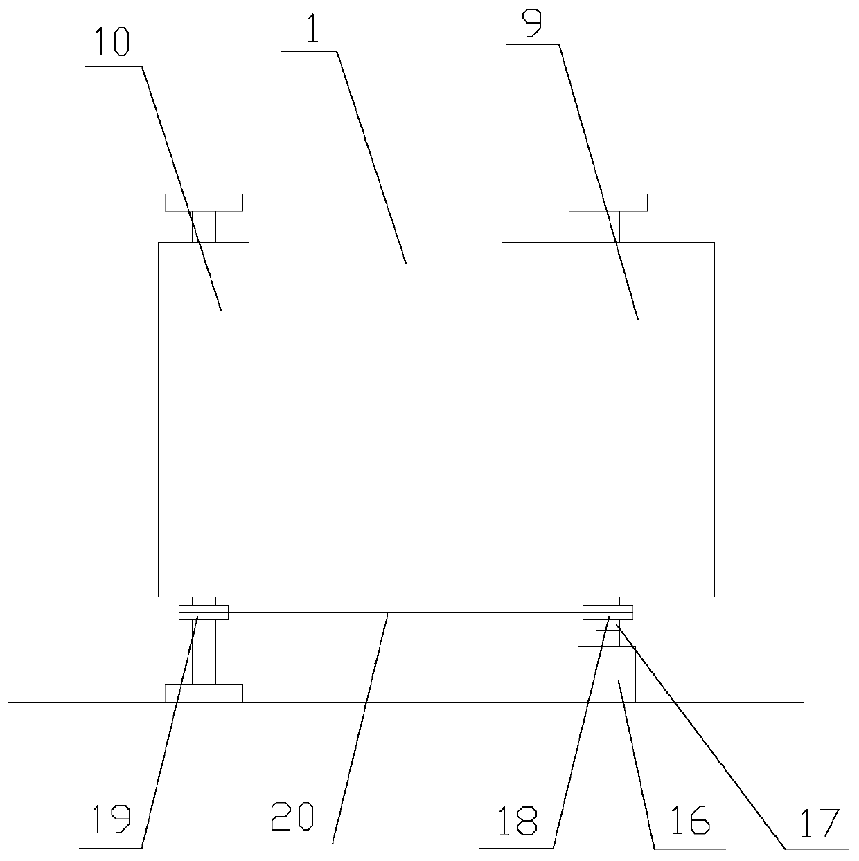
[0032] The present invention is described in further detail now in conjunction with accompanying drawing. These drawings are all simplified schematic diagrams, which only illustrate the basic structure of the present invention in a schematic manner, so they only show the configurations related to the present invention.

[0033] Such as figure 1 As shown, an unmanned ship for oil slick cleaning and recovery includes a hull 1, a fixed plate 2, a recovery box 3, a solar drive mechanism, a cleaning mechanism and a winching mechanism, and the fixed plate 2 is arranged on the hull 1 On one side, the fixed plate 2 is provided with a recovery port, the recovery box 3 is arranged below the fixed plate 2, the solar drive mechanism and the cleaning mechanism are all arranged on the hull 1, and the twisting mechanism is arranged on the fixed plate 2 superior;

[0034] The unmanned ship is driven by the solar drive mechanism, the control of the unmanned ship is realized by the remote con...


PUM


Abstract

The invention relates to an unmanned ship for floating oil cleaning and recycling. The unmanned ship for floating oil cleaning and recycling comprises a ship body, a fixed plate, a recycling tank, a solar energy drive mechanism, a cleaning mechanism and a wringing mechanism. According to the unmanned ship for floating oil cleaning and recycling, the operation of a device on the unmanned ship is supplied with power generated through a solar panel, and the clean energy is used, so that energy conservation and environment protection are realized; through remote control, people is prevented from touching floating oil, so that the health of a human body is protected; compared with an existing device for cleaning the floating oil by using an oil absorption felt, the manual replacement of the oilabsorption felt is avoided, the time is saved, and the working efficiency is improved; and through the wringing mechanism, the floating oil on the oil absorption felt is wrung out , so that comparedwith an existing device for cleaning the oil absorption felt, the wringing device realizes a series of operations such as pulling, squeezing and wringing, the floating oil on the oil absorption felt is cleaned thoroughly, the assembly-line type integrated operation is adopted for floating oil cleaning, floating oil recycling and oil absorption felt reutilizing, and practicability is realized.

Description

technical field [0001] The invention relates to an unmanned ship used for oil slick cleaning and recovery. Background technique [0002] The oil slick recovery device is a device for cleaning and recovering the oil slick on the water surface. Ships and industrial production will produce oily sewage leakage and discharge, causing oil pollution on the water surface, not only polluting ships, docks, beaches and other infrastructure, It is also easy to cause fire, especially the oil film destroys the circulation of oxygen, seriously damages aquatic resources, and brings great harmful effects to the human living environment. At present, two methods of recovery and dissipation are generally used to clean up oil slicks. For large areas Generally, oil-absorbing felts are used for the recovery of oil slicks for adsorption and recovery. When oil-absorbing felts are used for oil slick treatment, the oil-absorbing felts need to be replaced frequently, which is time-consuming and laborio...

Claims


Application Information

Patent Timeline
IPC IPC(8): E02B15/10B63B35/32E02B15/04
CPCB63B35/32B63B2035/008E02B15/046E02B15/10Y02A20/204
Inventor 胡佳琪
Owner 广州市欧伊若科技有限公司
Learn More