


Quick Research
Generate reliable direction feasibility study reports for your R&D in just a few steps.

Technical Q&A
Discover and master advanced knowledge NOW. Basics, ideas, possibilities, all at once.

Find Solutions
As an expert in R&D theories, this can generate solutions to your technical problems instantly.

Evaluate Feasibility
Analyze your overall solution with one click, know your potential R&D risks in advance.

Monitor Landscape
Get weekly tech updates, stay abreast of the latest tech innovations and key insights.
Water pouring device with high safety
A safety and mounting rack technology, applied in liquid flow control devices, distribution devices, special distribution devices, etc., can solve problems such as scalding hands, pouring boiling water, etc. slowing effect
- Summary
- Abstract
- Description
- Claims
- Application Information
AI Technical Summary
Problems solved by technology
Method used
Image

Examples
Embodiment 1
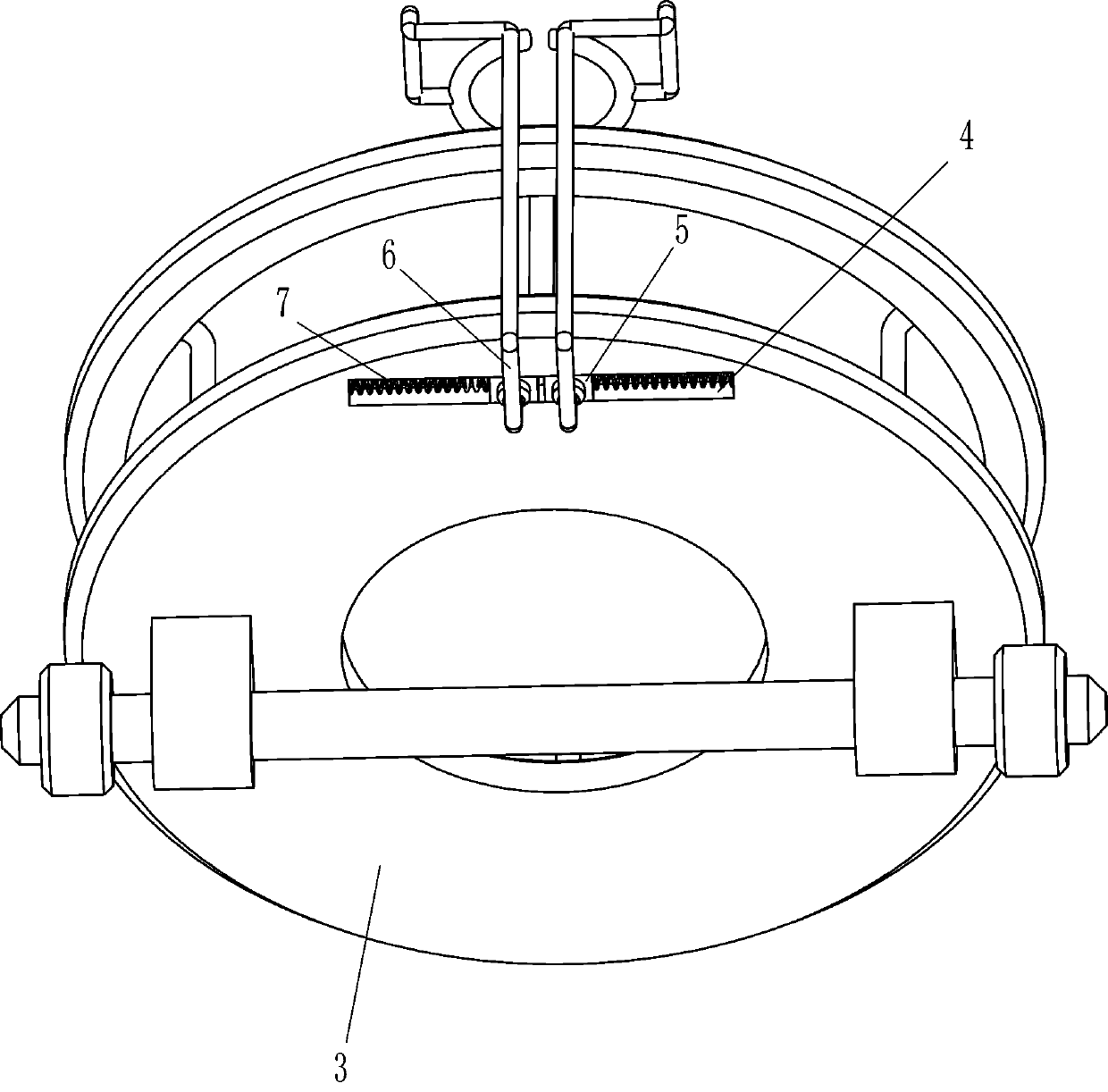
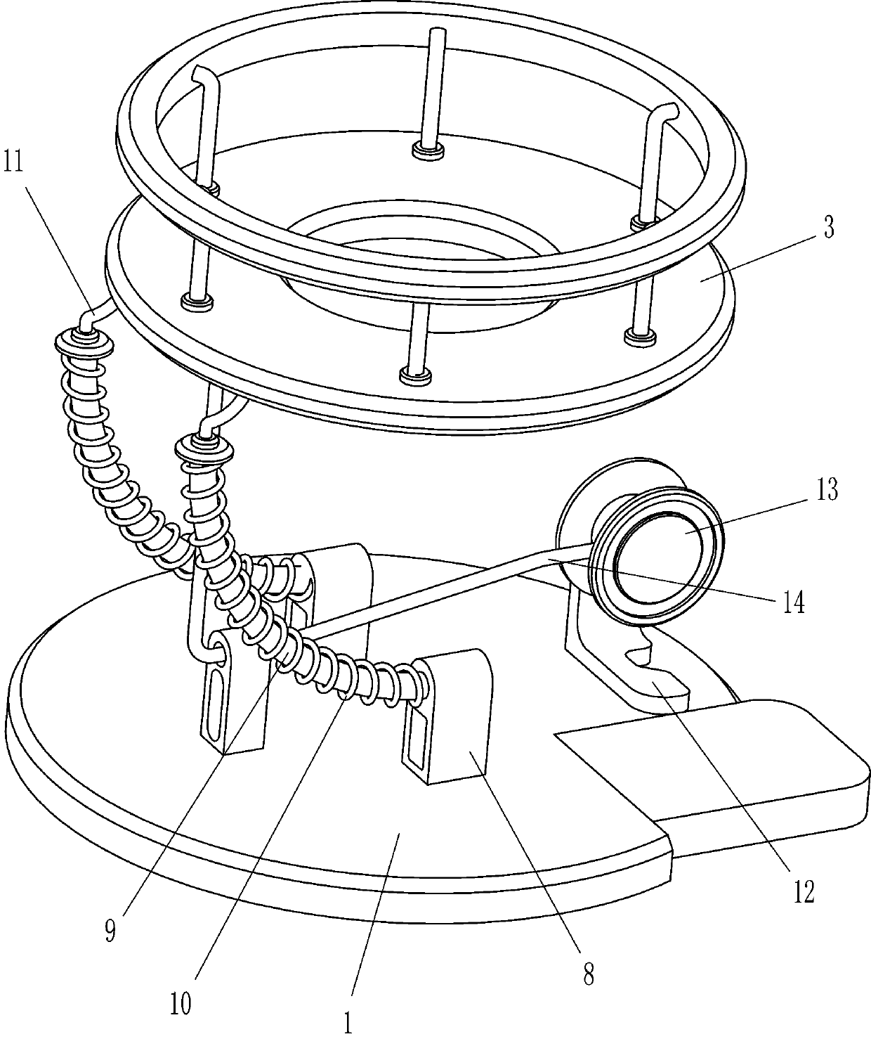
[0024] A water pouring device with high safety, such as Figure 1-6 As shown, it includes a base 1, a bracket 2, a placement frame 3, a handle fixing component, a guide component, a water cup placement component, a take-up and release line component, and a power component. 2 There is a rack 3 rotating between the tops, and a handle fixing assembly that fixes the handle by sliding is installed on the right side of the bottom of the rack 3, and a guide for pouring water into the kettle is provided between the base 1 and the rack 3 Guide assembly, the top left side of the base 1 is provided with a water cup placement assembly, the top right side of the base 1 is installed with a take-up and release line assembly through rotation, the take-up and release assembly cooperates with the guide assembly, and the top right side of the base 1 is installed with a Power components that are powered by electric motors.
[0025] Such as figure 1 and 2 As shown, the handle fixing assembly in...
Embodiment 2
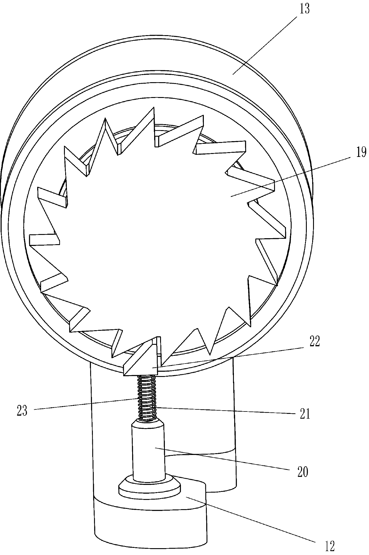
[0037] On the basis of Example 1, such as figure 1 and 7 As shown, it also includes a second sliding block 26, a special-shaped rod 27, a deceleration plate 28, a rotating rod 29, a third spring 30, a pulling rod 31 and a pressing rod 32, and the upper part of the rear side of the mounting frame 12 has a second sliding groove 25 , the left and right sides of the second sliding groove 25 are slidingly provided with a second sliding block 26, the second sliding block 26 is welded with a special-shaped rod 27, the upper end of the special-shaped rod 27 is welded with a speed reducer 28, and the rear side of the reel 13 The output shaft of the output shaft is connected with a rotating rod 29, the rotating rod 29 is located between the deceleration plates 28, the third spring 30 is welded between the second sliding blocks 26, and the bottom of the second sliding block 26 is rotatably provided with a pull rod 31, pulling A pressing bar 32 is rotatably arranged between the bottom en...
PUM
 Abstract
Description
Claims
Application Information
 - R&D Engineer
- R&D Manager
- IP Professional
- Industry Leading Data Capabilities
- Powerful AI technology
- Patent DNA Extraction
Browse by: Latest US Patents, China's latest patents, Technical Efficacy Thesaurus, Application Domain, Technology Topic, Popular Technical Reports.
© 2024 PatSnap. All rights reserved.Legal|Privacy policy|Modern Slavery Act Transparency Statement|Sitemap|About US| Contact US: help@patsnap.com