a mechanical arm

A technology of mechanical arms and support arms, which is applied in the field of manipulators, can solve the problems of low adsorption and fit, weak point of force on arc-shaped cylinders, and sliding of cylinders, etc., and achieve the effect of firmness of cylindrical objects

Active Publication Date: 2021-08-27
SHANDONG SHENLI RIGGING
View PDF7 Cites 0 Cited by
  • Summary
  • Abstract
  • Description
  • Claims
  • Application Information

AI Technical Summary

Problems solved by technology

[0002] Robotic arms are widely used in industrial manufacturing, medical treatment, space exploration and other fields. Although their shapes are different, they can all accept instructions and accurately locate a certain point in three-dimensional or two-dimensional space for operations. The robotic arm has the ability to carry It has the function of heavy objects, and can carry objects of various shapes. However, when the existing mechanical arm is carrying cylindrical objects, the shape of the cylindrical object is long, so it can only be carried by grasping the object column, but when carrying During the process, the sucker-type gripper has a low degree of adsorption and fit on the arc surface of the column body, resulting in poor gripping effect, and when the disc-shaped gripper is working, because the circular gripper is arc-shaped, it will cause the arc-shaped column When the body is grasped, the point of force is weak, and the inertial force generated by the movement of the mechanical arm will cause the body to slide slightly

Method used


Image

  • a mechanical arm
  • a mechanical arm
  • a mechanical arm

Examples


Embodiment 1

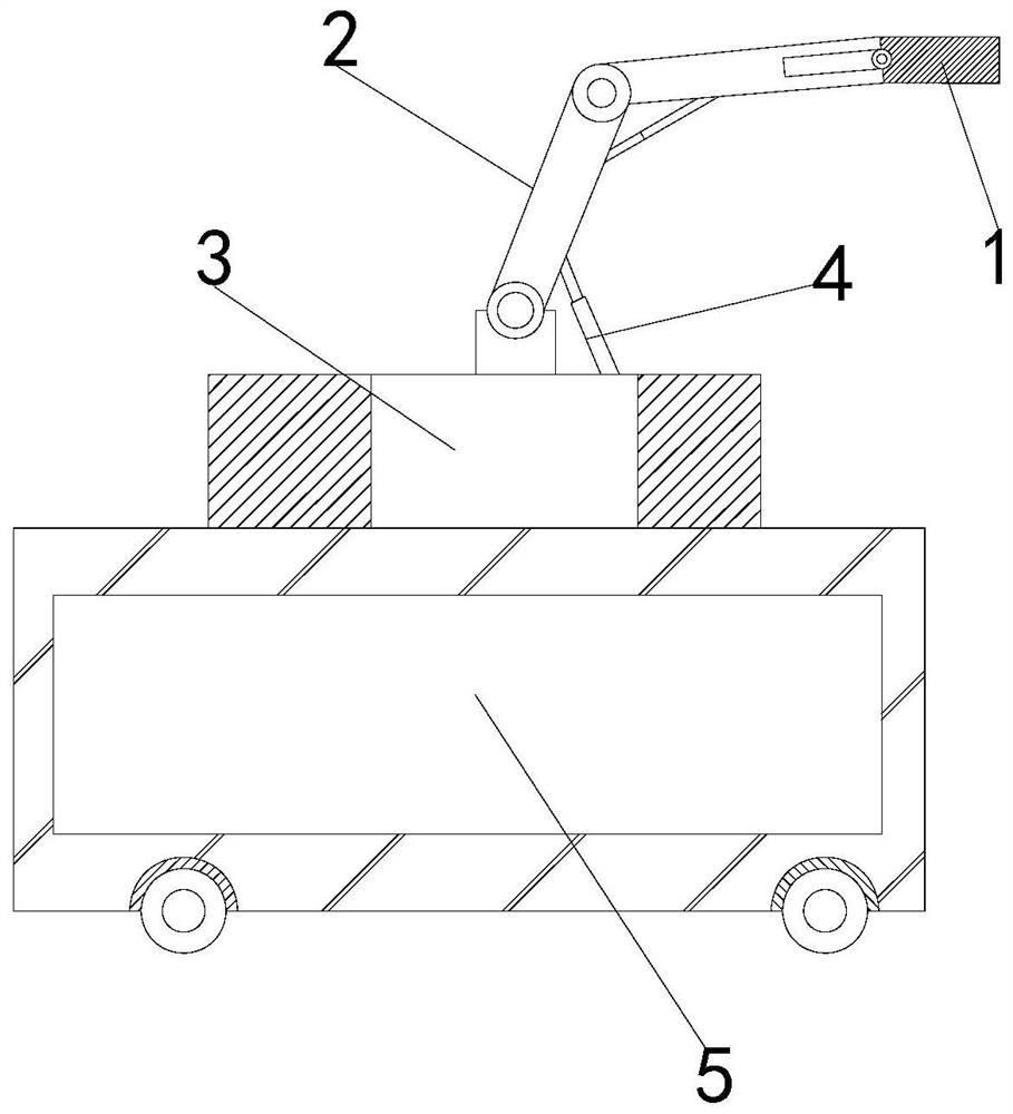
[0023] Such as Figure 1-Figure 4 Shown:

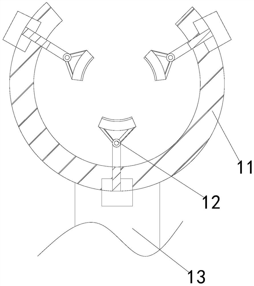
[0024] A kind of mechanical arm of the present invention, its structure comprises gripper 1, support arm 2, swing cylinder 3, telescoping rod 4, fixed platform 5, described support arm 2 is hingedly connected with gripper 1, and described support arm 2 is fixed on the swing Above the cylinder 3, the swing cylinder 3 and the fixed table 5 are an integrated structure, the telescopic rod 4 is located above the swing cylinder 3, and the gripper 1 is provided with a connecting rod 11, a fixing mechanism 12, and a force rod 13. The fixing mechanism 12 is installed on the upper end of the connecting rod 11, and the connecting rod 11 is welded on the upper end of the force-bearing rod 13. The fixing mechanism 12 is circularly distributed on the connecting rod 11, and is in the shape of an isosceles triangle, which has a more stable effect, making Cylindrical objects hold better.

[0025] Wherein, the fixed mechanism 12 is provided with a fo...

Embodiment 2

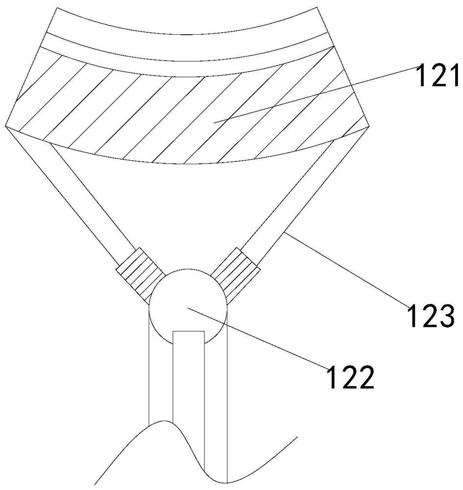
[0030] Such as Figure 5-Figure 7 Shown:

[0031] Wherein, the stressed mechanism 121 is provided with a pressure block b1, a stressed block b2, a pressure rod b3, a connecting block b4, and an elastic groove b5, the pressure block b1 is welded on the upper end of the stressed block b2, and the pressure rod b3 is installed inside the connection block b4, there are two connection blocks, and they are symmetrically distributed at the left and right ends of the elastic groove, and there are two pressure rods, which are symmetrically distributed through the force block, and the pressure rod b3 makes the effect The force is concentrated on the upper end of the force block b2.

[0032] Wherein, the pressure block b 1 is provided with a compression mechanism b 11 and a connection plate b 12, the compression mechanism b 11 is attached above the connection plate b 12, the connection plate is made of rubber material, and its surface shape is rough, with a The role of high friction can...


PUM


Abstract

The invention discloses a mechanical arm, the structure of which includes a gripper, a support arm, a swing cylinder, a telescopic rod, and a fixed platform. The support arm is hinged to the gripper, the support arm is fixed above the swing cylinder, and the swing cylinder is integrated with the fixation platform. The telescopic rod is located above the swing cylinder, and the gripper is equipped with a connecting rod, a fixing mechanism, and a force rod. Through the fixing mechanism on the gripper, the cylindrical object is more stable during the handling process, and it is effective for controlling the power rod to the limit block. Push to make the limit block move on the moving groove. Since the transmission rod penetrates through the rotation block and the limit block is limited and engaged, the rotation block is fixed. Since the fixing mechanism is distributed on the handle in an isosceles triangle ring, According to the principle that the triangle is more stable, a more stable effect is achieved. The compression mechanism on the pressure block compresses the cylindrical object, making the left side of the rubber block into a sealed state, and the pressure becomes smaller, and then the force of the compression block plus the suction makes it Cylindrical objects are stronger.

Description

technical field [0001] The invention relates to the field of manipulators, in particular to a manipulator. Background technique [0002] Robotic arms are widely used in industrial manufacturing, medical treatment, space exploration and other fields. Although their shapes are different, they can all accept instructions and accurately locate a certain point in three-dimensional or two-dimensional space for operations. The robotic arm has the ability to carry It has the function of heavy objects, and can carry objects of various shapes. However, when the existing mechanical arm is carrying cylindrical objects, the shape of the cylindrical object is long, so it can only be carried by grasping the object column, but when carrying During the process, the sucker-type gripper has a low degree of adsorption and fit on the arc surface of the column body, resulting in poor gripping effect, and when the disc-shaped gripper is working, because the circular gripper is arc-shaped, it will ...

Claims


Application Information

Patent Timeline
Patent Type & Authority Patents(China)
IPC IPC(8): B65G61/00B65G47/91
CPCB65G47/91B65G61/00
Inventor 杜大平张体学牟立兵
Owner SHANDONG SHENLI RIGGING
Why Eureka
Try Eureka