
Plate directional arranging and conveying device for punch press

A technology of directional arrangement and conveying device, which is applied in the field of plate processing, can solve the problems of high mental tension, inability to automatically correct, low efficiency, etc.

Active Publication Date: 2020-08-07
山东惠民鲁盛金属制品有限公司
View PDF7 Cites 21 Cited by
  • Summary
  • Abstract
  • Description
  • Claims
  • Application Information

AI Technical Summary

Problems solved by technology

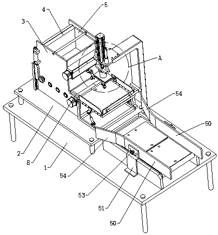
[0002] In the prior art, the feeding of the punching machine is usually arranged and transported to the designated position through the feeding conveyor, and then the processed workpiece is placed on the lower die of the punching machine by a manipulator or manually for processing. When one type of plate is being processed, the plate The processing direction of the workpiece needs to be corrected. However, the existing conveying method cannot be corrected automatically. Generally, it is manually corrected in the later stage, and then put on the feeding conveyor for loading. Therefore, the labor intensity of the workers is high and the work When thinking is highly tense, people are prone to fatigue, and the efficiency is low. We propose a device for directional arrangement and conveying of plate parts for punching machines, in order to solve the above-mentioned problems.

Method used


Image

  • Plate directional arranging and conveying device for punch press
  • Plate directional arranging and conveying device for punch press
  • Plate directional arranging and conveying device for punch press

Examples


Embodiment Construction

[0028] In order to make the object, technical solution and advantages of the present invention clearer, the present invention will be further described in detail below in conjunction with the accompanying drawings and embodiments. It should be understood that the specific embodiments described here are only used to explain the present invention, not to limit the present invention.

[0029] In the description of the present invention, it should be noted that the terms "center", "upper", "lower", "left", "right", "front", "rear", "vertical", "horizontal", The orientation or positional relationship indicated by "inner", "outer", etc. is based on the orientation or positional relationship shown in the drawings, and is only for the convenience of describing the present invention and simplifying the description, rather than indicating or implying that the referred device or element must have Certain orientations, constructed and operative in certain orientations, therefore are not t...


PUM


Abstract

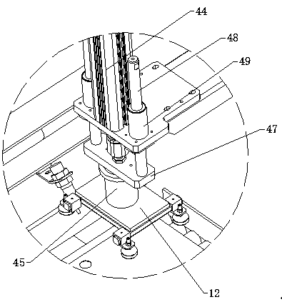
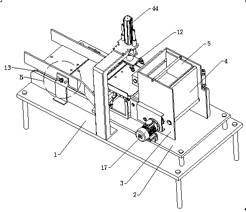
The invention relates to the technical field of plate machining, in particular to a plate directional arranging and conveying device for a punch press. The plate directional arranging and conveying device for the punch press comprises a base, and further comprises a placing and discharging mechanism, a directional correcting mechanism and a conveying mechanism, wherein the placing and dischargingmechanism comprises a supporting table and a rectangular placing box, a turnover door is arranged at the open end of one side of the placing box, abutting vertical plates are arranged on the two sidesof the interior of the placing box, three feeding rolling wheels are arranged at the lower end of the interior of the placing box, a discharging opening is formed in the lower end of the surface, away from the turnover door, of the placing box, extending vertical plates are arranged below the two sides of the surface, away from the turnover door, of the placing box, and opposite blocks are arranged between the two extending vertical plates; the directional correcting mechanism comprises a detection camera, a detection turnover slide way and a correcting assembly, and the correcting assembly comprises a pneumatic suction disc; and the conveying mechanism comprises a feeding conveyor and two material guiding assemblies. According to the technical scheme, the direction of plates can be automatically corrected, the plates are directionally arranged and conveyed, and the conveying efficiency is improved.

Description

technical field [0001] The invention relates to the technical field of plate processing, in particular to a plate orientation arrangement conveying device for a punching machine. Background technique [0002] In the prior art, the feeding of the punching machine is usually arranged and transported to the designated position through the feeding conveyor, and then the processed workpiece is placed on the lower die of the punching machine by a manipulator or manually for processing. When one type of plate is being processed, the plate The processing direction of the workpiece needs to be corrected. However, the existing conveying method cannot be corrected automatically. Generally, it is manually corrected in the later stage, and then put on the feeding conveyor for loading. Therefore, the labor intensity of the workers is high and the work When the mind is highly tense, people are prone to fatigue, and the efficiency is low. We have proposed a plate directional arrangement con...

Claims


Application Information

Patent Timeline
Patent Type & Authority Applications(China)
IPC IPC(8): B65G47/52B65G47/82B65G47/24B65G47/90
CPCB65G47/24B65G47/52B65G47/82B65G47/90
Inventor 骆玲玲崔新林
Owner 山东惠民鲁盛金属制品有限公司
Learn More