A cardboard automatic thin knife slitting device
A slitting device and automatic technology, applied in metal processing and other directions, can solve problems such as unfavorable spindle stability, affecting cutting quality, and large driving weight, and achieve the effect of being beneficial to use, high adaptability, and ensuring stability
Active Publication Date: 2022-05-31
四川宏图风景环保科技有限公司
View PDF3 Cites 0 Cited by
- Summary
- Abstract
- Description
- Claims
- Application Information
AI Technical Summary
Problems solved by technology
[0003] However, in the existing slitting devices, most of the slitting knives are directly installed on the main shaft, and then driven up and down to connect, so that not only is it not conducive to guiding and compressing the cardboard when it is used again, but it is easy to shift and misplace and affect the cutting quality. The up and down adjustment needs to drive the frame and the main shaft to move synchronously. The driving weight is heavy, which is not conducive to ensuring the stability of the main shaft. Moreover, all slitting knives need to be adjusted synchronously, which is poor in practicability. A new slitting device needs to be proposed
Method used
View moreImage
Smart ImageViewing Examples
Examples
Embodiment Construction
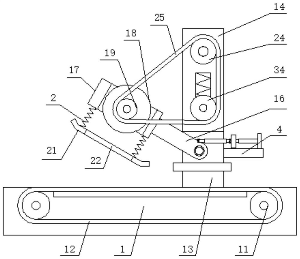
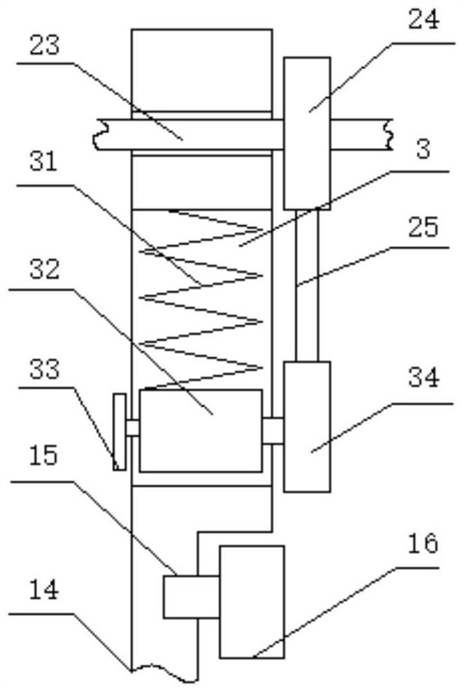
[0029] Please refer to FIG. 2, the other end of the fixed plate 14 is rotatably installed with a main shaft 23, and the surface of the main shaft 23 is installed with an active
Login to View More PUM
 Abstract
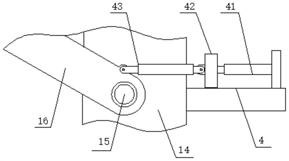
The invention discloses a cardboard automatic thin-knife slitting device, which comprises a machine frame. Both ends of the machine frame are rotatably equipped with conveying rollers. A mounting plate is fixedly installed, the other side surface of the mounting plate is fixedly connected with a fixed plate, one side surface of the fixed plate is hinged with an inclined connecting plate through a hinge seat, and the other end of the inclined connecting plate is fixedly connected with a mounting plate. A slitting knife is mounted on the side of the mounting frame, the shaft end of the slitting knife is fixedly mounted with a driven pulley, the other side surface of the mounting frame is fixedly connected with a connecting spring, and the connecting spring The other end of the utility model is fixedly installed with an auxiliary pressure plate, and the side of the auxiliary pressure plate is provided with a long cutting groove, which can greatly improve the convenience and stability of use, and ensure safety and high efficiency.
Description
A cardboard automatic thin knife slitting device technical field [0001] The present invention relates to the field of slitting devices, and more particularly, to a slitting device for automatic thin-knife cardboard. Background technique In the production process of corrugated paper, it is necessary to cut and divide, and this needs to use a knife slitting device, which can The roll of cardboard is cut lengthwise and divided into different widths for use. [0003] But in the existing slitting device, most of the slitting knives are directly installed on the main shaft, and then the upper and lower drives are connected to connect, In this way, it is not only unfavorable for guiding and pressing the cardboard, but also easy to shift and dislocate and affect the cutting quality. The adjustment needs to drive the frame and the main shaft to move synchronously. The weight of the drive is large, which is not conducive to ensuring the stability of the main shaft. Synchronous...
Claims
Login to View More Application Information
Patent Timeline
 Patent Type & Authority Patents(China)
IPC IPC(8): B26D1/04B26D7/00B26D7/26
CPCB26D1/045B26D7/0006B26D7/2628
Inventor 粱应积
Owner 四川宏图风景环保科技有限公司
Features
- Generate Ideas
- Intellectual Property
- Life Sciences
- Materials
- Tech Scout
- Unparalleled Data Quality
- Higher Quality Content
- 60% Fewer Hallucinations
Learn More Browse by: Latest US Patents, China's latest patents, Technical Efficacy Thesaurus, Application Domain, Technology Topic, Popular Technical Reports.
© 2025 PatSnap. All rights reserved.Legal|Privacy policy|Modern Slavery Act Transparency Statement|Sitemap|About US| Contact US: help@patsnap.com


