
Equipment and method for sieving and deironing pug for manufacturing power insulator

A technology of insulators and mud materials, applied in chemical instruments and methods, magnetic separation, solid separation, etc., can solve the problems of poor screening effect of the device, manual separation, and inability to achieve complete separation of iron ore, so as to ensure the screening rate and avoid the leakage of the screen Effect

Inactive Publication Date: 2020-08-07
潘学勇
View PDF14 Cites 0 Cited by
  • Summary
  • Abstract
  • Description
  • Claims
  • Application Information

AI Technical Summary

Problems solved by technology

[0003] However, there are the following problems in the use of the mud sieving and iron removal equipment for making power insulators in the current market. Then when the traditional device is working, the screened iron sand will be adsorbed on one side of the magnet. When the device runs for a certain period of time, it is necessary to manually separate the screened iron sand. On the one hand, it reduces the continuity of the device’s work. On the other hand, due to the strong adsorption force of the magnet, the complete separation of the iron sand cannot be achieved when the scraper is used to manually remove it; b. The existing power insulator making mud screening and iron removal equipment is screening the mud powder At this time, because the accumulation thickness of the mud powder cannot be effectively controlled, the accumulation thickness of the mud powder in some areas is relatively large, so that part of the iron sand at the top of the mud powder pile cannot be effectively separated, making the screening effect of the device poor

Method used


Image

  • Equipment and method for sieving and deironing pug for manufacturing power insulator
  • Equipment and method for sieving and deironing pug for manufacturing power insulator
  • Equipment and method for sieving and deironing pug for manufacturing power insulator

Examples


Embodiment Construction

[0028] In order to make the technical problems, technical solutions and beneficial effects to be solved by the present invention clearer, the present invention will be further described in detail below in conjunction with the accompanying drawings and embodiments. It should be understood that the specific embodiments described here are only used to explain the present invention, not to limit the present invention.

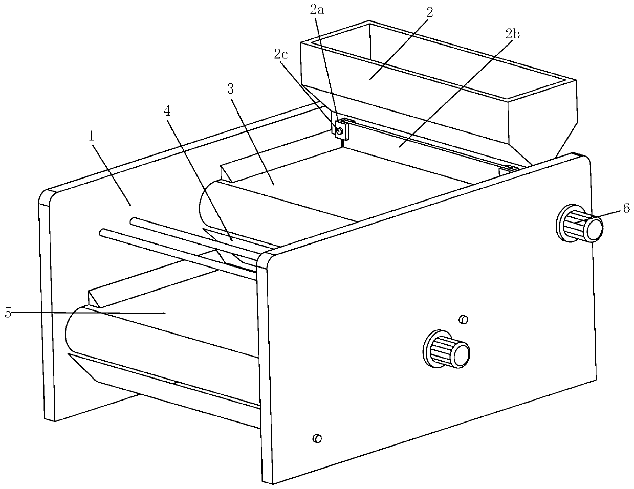
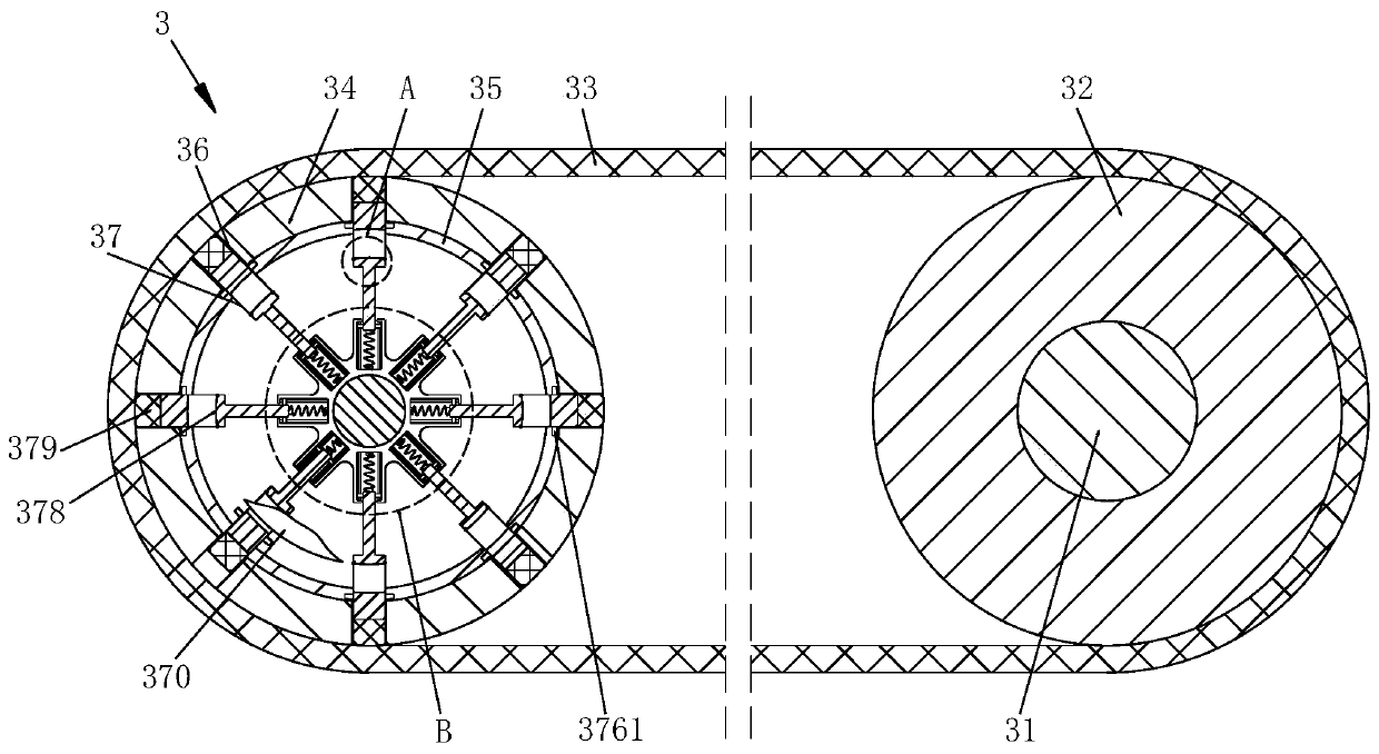
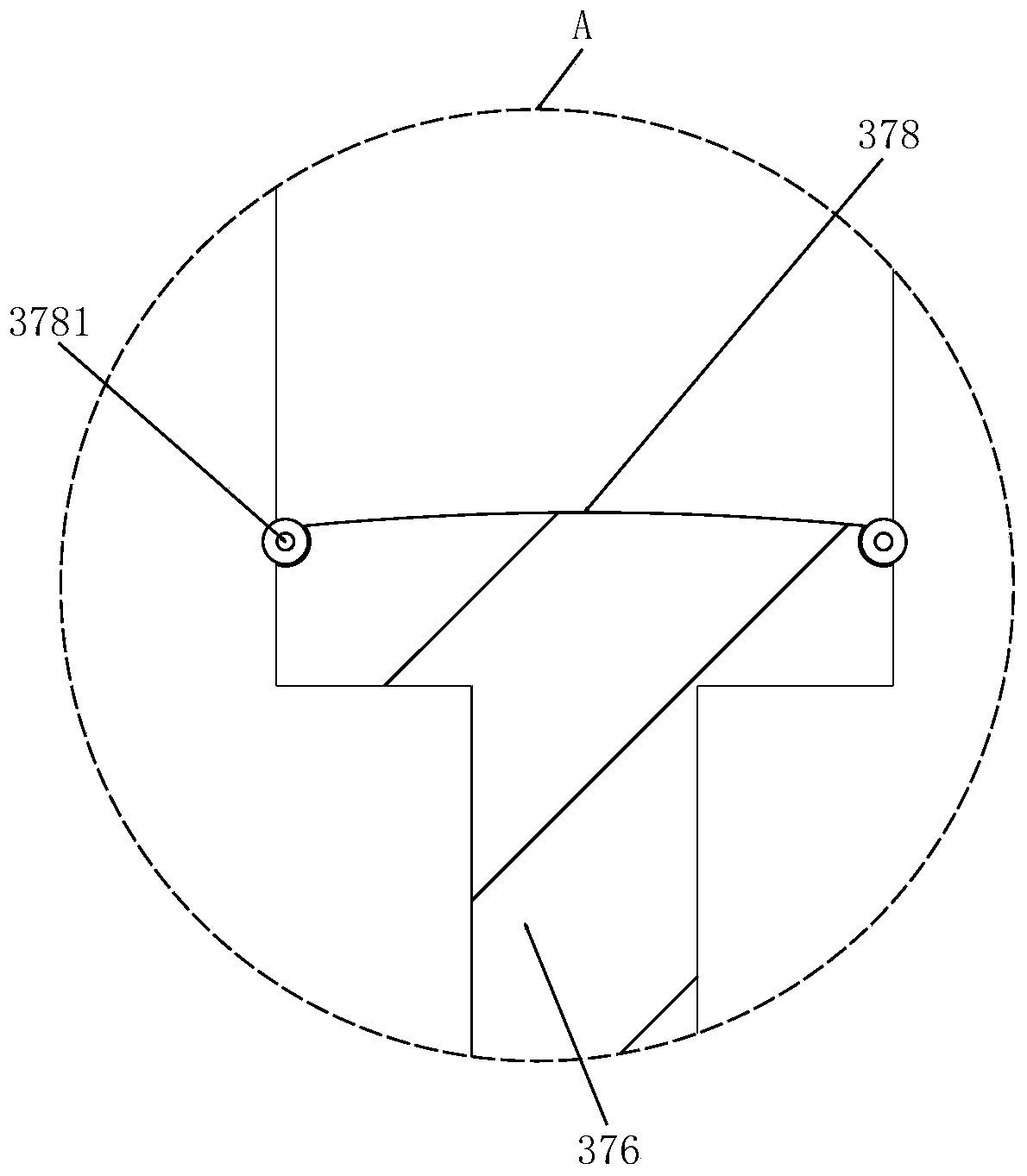
[0029] Such as Figure 1 to Figure 6 As shown, a power insulator making mud screening and iron removal equipment includes a fixed side plate 1, a feed hopper 2, a first screening mechanism 3, a deflector 4, a second screening mechanism 5 and a driving motor 6, two The fixed side plates 1 are connected and fixed by fixed rods, the feed hopper 2 is located on the upper side of the two fixed side plates 1, and both sides of the bottom of the feed hopper 2 are fixed to the fixed side plates 1 by bolts. The side wall, the bottom of the feed hopper 2 is provided with a ...


PUM


Abstract

The invention relates to equipment and a method for sieving and deironing pug for manufacturing a power insulator. The equipment comprises two fixed side plates, a feeding hopper, a first screening mechanism, a guide plate, a second screening mechanism and driving motors. The two fixed side plates are connected and fixed through a fixed rod; the feeding hopper is positioned on the upper sides of the two fixed side plates; the two sides of the bottom of the feeding hopper are fixed to side walls of the fixed side plates through bolts, the first screening mechanism is arranged below the feedinghopper; the second screening mechanism is arranged on a lower left portion of the first screening mechanism, two ends of the first screening mechanism and two ends of the second screening mechanism are connected with the side walls of the fixed side plates, The driving motors are installed on the outer wall sides of the fixed side plates, the two driving motors are connected with the first screening mechanism and the second screening mechanism correspondingly, flow guide plates are arranged at the lower left ends of the first screening mechanism and the second screening mechanism correspondingly, the iron sand automatic separation effect is achieved, the working continuity of the device is guaranteed, and the screening rate is high.

Description

technical field [0001] The invention relates to the technical field of electric power equipment, in particular to a device and method for sieving and removing iron from mud for making electric insulators. Background technique [0002] Insulators are special insulation controls that can play an important role in overhead transmission lines. In the early years, insulators were mostly used on utility poles, and gradually developed into a high-voltage wire connection tower with many disc-shaped insulators hanging on one end. It is used to increase the creepage distance, usually made of glass or ceramics, and is called an insulator. In ceramic insulators, ceramic insulators are made of mud through a series of processes such as grinding, screening, dehydration, mud refining and firing. Among them, in the screening process, the iron sand mixed with mud powder is mainly sieved to ensure the absolute insulation effect of the later ceramic insulators. [0003] However, there are the...

Claims


Application Information

Patent Timeline
Patent Type & Authority Applications(China)
IPC IPC(8): B03C1/18
CPCB03C1/18
Inventor 潘学勇刘云华
Owner 潘学勇
Learn More