
Method and device for filling containers with carbonised filling material and subsequently closing the filled containers

A filling and container technology, which is applied in the direction of closing the container tightly with a lid, closure, packaging item type, etc., can solve the problems of high structural design costs, and achieve the effect of minimizing the risk of pollution

Active Publication Date: 2020-08-04
KHS GMBH
View PDF9 Cites 0 Cited by
  • Summary
  • Abstract
  • Description
  • Claims
  • Application Information

AI Technical Summary

Problems solved by technology

A disadvantage is that the filling head moves laterally into the pressure chamber, which requires a relatively high construction effort

Method used


Image

  • Method and device for filling containers with carbonised filling material and subsequently closing the filled containers
  • Method and device for filling containers with carbonised filling material and subsequently closing the filled containers
  • Method and device for filling containers with carbonised filling material and subsequently closing the filled containers

Examples


Embodiment Construction

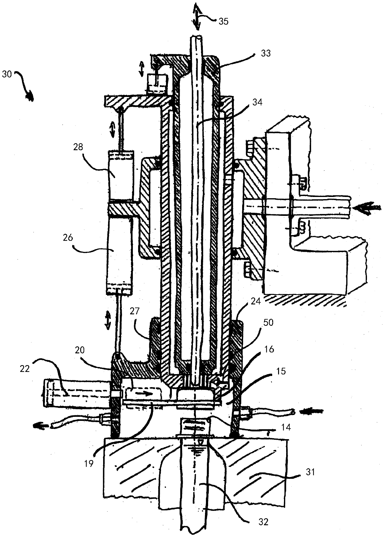
[0036] The basic structure of machines for filling containers or for simultaneously forming and filling containers from preforms is sufficiently known from the prior art. In order to avoid repetitions, reference is made to DE 10 2010 007 541 A1 with respect to the forming and filling machine, especially to paragraphs [0028] to [0065] there and to the figure 1 to 8. In this regard, only the features that are essential to the invention are described below.

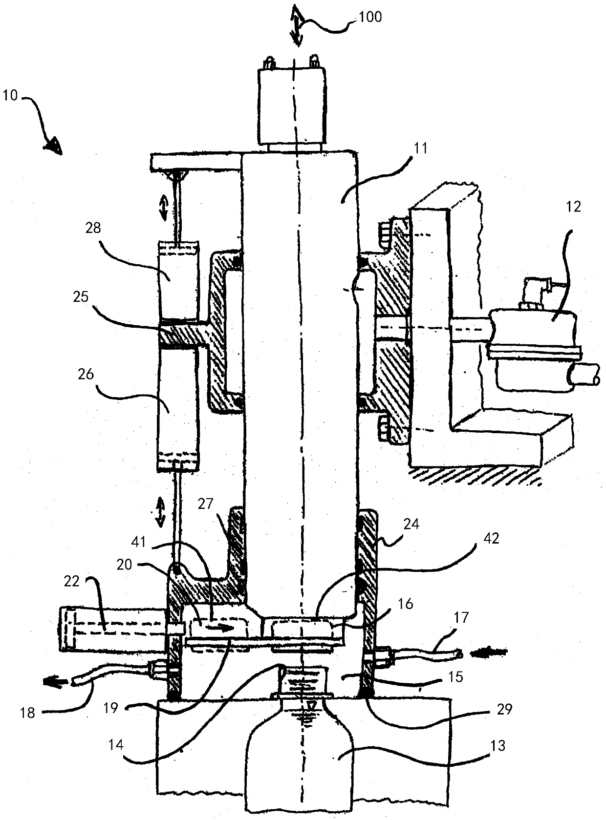
[0037] figure 1 A schematic illustration of a filling station 10 is shown with a filling head 11 arranged displaceably in the axial direction, which can be loaded with a filling product to be filled via a feed line 12 . Furthermore, a container 13 is shown, which is arranged in its filling position. Inside the pressure chamber 15 is located the container opening 14 which is aligned with the filling head side. The pressure chamber 15 surrounds both the container opening 14 and the end 16 of the filling head 11 facing the ...


PUM


Abstract

The invention relates to a method for filling a container (13, 32) with carbonised liquid filling material and for closing the filled container, in which in a filling station (10, 30) the filling material is introduced into the container (13, 32) by a filling head (11, 33) with a defined filling pressure, the filling head (11, 33) being initially moved out of a rest position, which allows deliveryand insertion of a container (13, 32) into the filling station (10, 30), into a work position at the inserted container in which an end region (16) of the filling head seals the opening (14) of the container, the container (13, 32) is then filled, after the conclusion of the filling phase the filling head (11, 33) is again moved out of the work position into a rest position spaced apart from thecontainer (13, 32) and the container (11, 33) is then closed in the filling station (11, 33) by a closure cap (20) at least to such an extent that no more filling material can exit, and the container(11, 33) is then removed from the filling station (11, 33), characterised in that, before the lifting of the filling head (11, 33) from the work position into the rest position spaced apart from the container (13), in a pressure chamber (15) of the filling station (10, 30) surrounding the opening (14) of the container (13, 32) a positive pressure between the ambient pressure and the filling pressure is set, which is selected such that any foaming of the filling material located in the container (13, 32) is minimised to such an extent that no filling material exits from the container (13, 32) when the filling head (11, 33) is raised out of the work position after the filling operation.

Description

technical field [0001] The invention relates to a method according to the preamble of claim 1 and a device according to the preamble of claim 9 . Background technique [0002] So-called filling stations are used in the usual method for filling containers at higher production speeds. The filling station is arranged, for example, on a working wheel which cooperates with suitable devices for feeding empty containers and removing filled containers. Here, the empty containers are first inserted into the filling station. In a next step, the filling head arranged in the filling station is lowered into an operating position over the opening of the container and seals the opening. In this working position, a filling process takes place in which the filling product is introduced under pressure into the container via the filling head. After filling, the filling head is moved into a rest position spaced apart from the container opening. The containers can then be removed and transpo...

Claims


Application Information

Patent Timeline
IPC IPC(8): B65B3/02B67B3/20B65B7/28B67C3/26B67C7/00
CPCB67B3/2066B67C3/2614B67C7/0073B29C2049/4664B29C2049/5813B29C2049/5858B29C49/58B29C49/06B67C2003/2697B29C2949/0715B29C49/12B29C49/4273B29C49/46B29L2031/712B67C3/06B67C7/00B67C2003/227B67C2003/2671B67C2003/2691
Inventor M·林克R·鲍姆加特M·利岑贝格B·雅伊泽尔F·贝格尔
Owner KHS GMBH
Learn More