A U-shaped demagnetization device

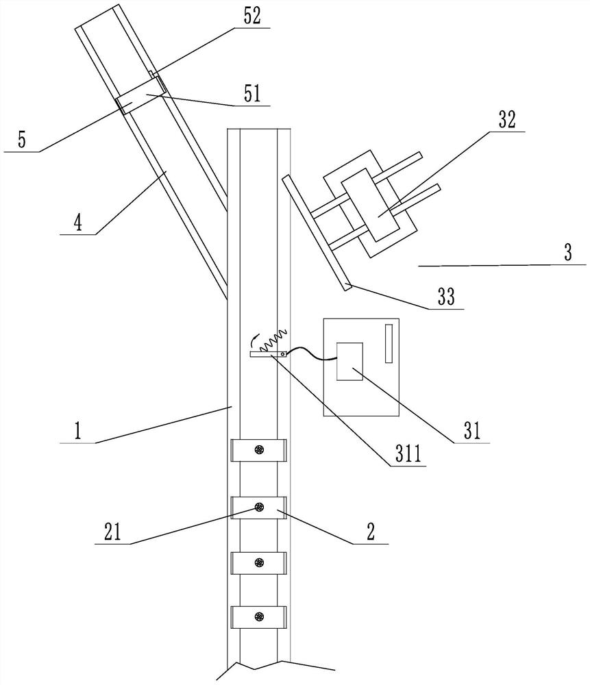
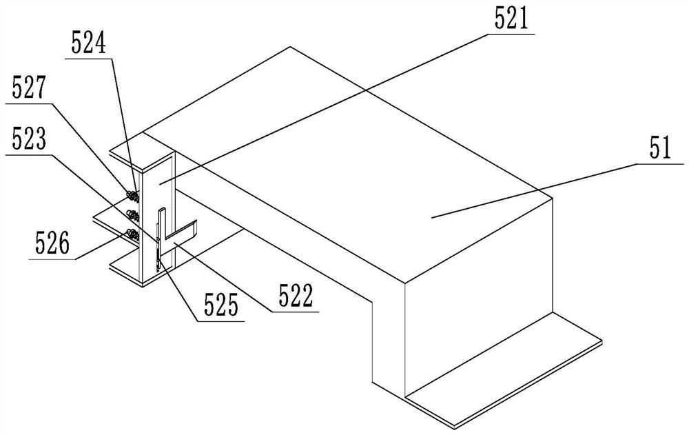
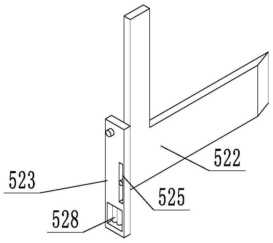
A U-shaped, demagnetization technology, applied in the direction of magnetic objects, magnetic performance measurement, transformer/inductance parts, etc., can solve the problems of poor demagnetization effect, short time for workpieces to pass through the demagnetizer, and undetectable workpieces, etc., to achieve increased Demagnetization time, quality improvement, effect of simple structure

Active Publication Date: 2021-11-05
SHANDONG LUCI IND TECH CO LTD
View PDF8 Cites 0 Cited by
  • Summary
  • Abstract
  • Description
  • Claims
  • Application Information

AI Technical Summary

Problems solved by technology

It has the following disadvantages: 1. The demagnetization effect is poor, the time for the workpiece to pass through the demagnetizer is short, and the demagnetization effect is not good; 2. The workpiece that still has residual magnetism after demagnetization cannot be detected, and the quality of the product cannot be guaranteed

Method used


Image

  • A U-shaped demagnetization device
  • A U-shaped demagnetization device
  • A U-shaped demagnetization device

Examples


Embodiment Construction

[0026] In order to clearly illustrate the technical features of the present solution, the present invention will be described in detail below through specific implementation methods and in conjunction with the accompanying drawings. The following disclosure provides many different embodiments or examples for implementing different structures of the present invention. To simplify the disclosure of the present invention, components and arrangements of specific examples are described below. Furthermore, the present invention may repeat reference numerals and / or letters in different instances. This repetition is for the purpose of simplicity and clarity and does not in itself indicate a relationship between the various embodiments and / or arrangements discussed. It should be noted that components illustrated in the figures are not necessarily drawn to scale. Descriptions of well-known components and processing techniques and processes are omitted herein to avoid unnecessarily lim...


PUM


Abstract

The invention discloses a U-shaped demagnetization device, which comprises a conveyor belt and a demagnetizer. The demagnetizer is U-shaped and installed above the conveyor belt. A plurality of demagnetizers are arranged on the conveyor belt, and a push device is arranged at the tail end of the conveyor belt. and a remanence conveyor belt, a remanence demagnetizer is provided on the remanence conveyor belt, the remanence demagnetizer includes a demagnetizer body and a blocking device, the blocking device includes a mounting plate, an adsorption plate and a blocking plate, and the adsorption plate is slidably arranged on the installation on the plate, and a spring is arranged between the adsorption plate and the mounting plate, the blocking plate is vertically arranged with the mounting plate, the upper end of the blocking plate is hinged with the mounting plate, a vertically arranged long hole is arranged in the middle of the blocking plate, and the rear of the adsorption plate A cylindrical sliding block is arranged at the end, and the sliding block is slidably arranged in the elongated hole. The invention has good demagnetization effect, and can detect workpieces still having residual magnetism for re-demagnetization treatment, thereby ensuring the demagnetization quality of the workpieces.

Description

technical field [0001] The invention relates to the technical field of demagnetization equipment, in particular to a U-shaped demagnetization device. Background technique [0002] The demagnetizer is a device used to eliminate the residual magnetism produced by machining. It generates magnetic force lines from electromagnetic coils, and directly or indirectly interferes with the magnetism of the original workpiece through the magnetic force lines to achieve demagnetization of the workpiece. [0003] In the prior art, the patent document with the notification number CN201886858U discloses a continuous demagnetizer, including a base, a conveyor belt is installed on the base, a gate-shaped demagnetizer is arranged above the conveyor belt, and the conveyor belt Pass through the gate demagnetizer. It has the following disadvantages: 1. The demagnetization effect is poor, the time for the workpiece to pass through the demagnetizer is short, and the demagnetization effect is not g...

Claims


Application Information

Patent Timeline
Patent Type & Authority Patents(China)
IPC IPC(8): H01F13/00H01F27/08G01R33/12
CPCG01R33/12H01F13/006H01F27/085
Inventor 陈敬锋陈敬省陈文杰
Owner SHANDONG LUCI IND TECH CO LTD
Why Eureka
Try Eureka