Vessel demagnetizing method
A technology for ships and demagnetization, applied in the directions of ships, ship weapons, attack devices, etc., can solve problems such as time-consuming and laborious, and achieve the effect of reducing labor intensity, improving emergency benefits, and restoring mobility.
- Summary
- Abstract
- Description
- Claims
- Application Information
AI Technical Summary
Problems solved by technology
Method used
Image
Examples
Embodiment 1
[0024] Example 1, a 2-ton ship, ship width B=1.5m, midship radial circumference L=5m, vertical component of local geomagnetic field Hz=20A / m, Hp=30A / m, to achieve the overall Demagnetization, including the following steps:
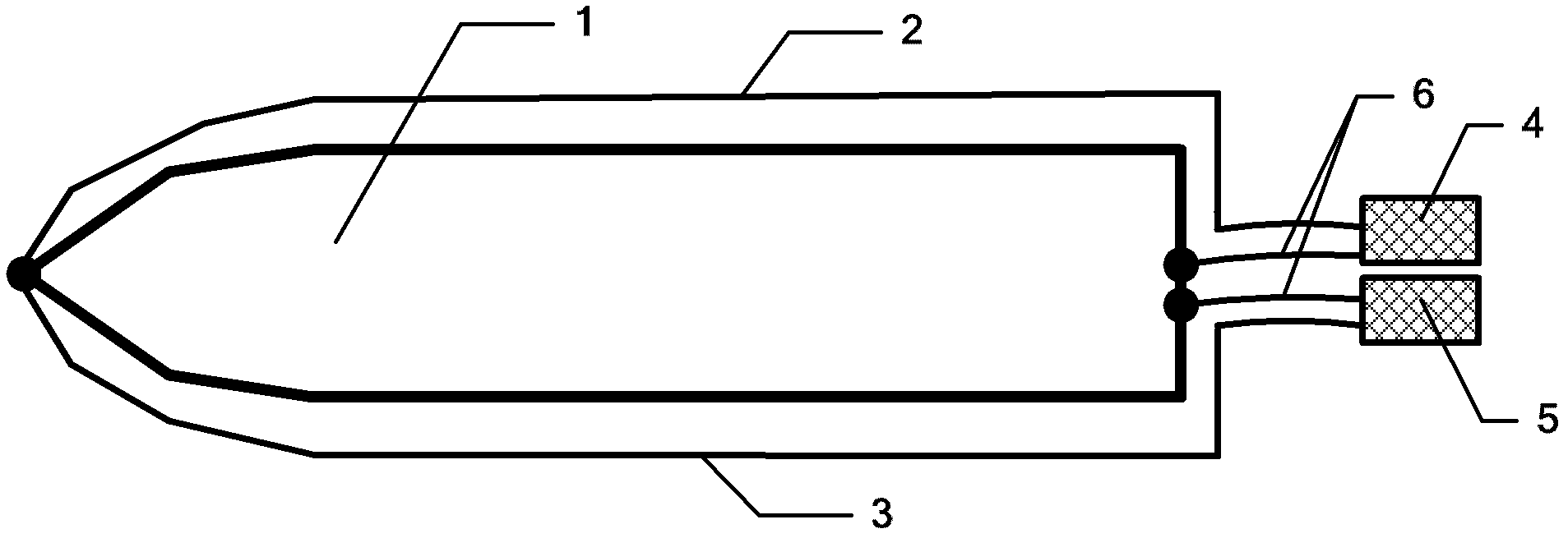
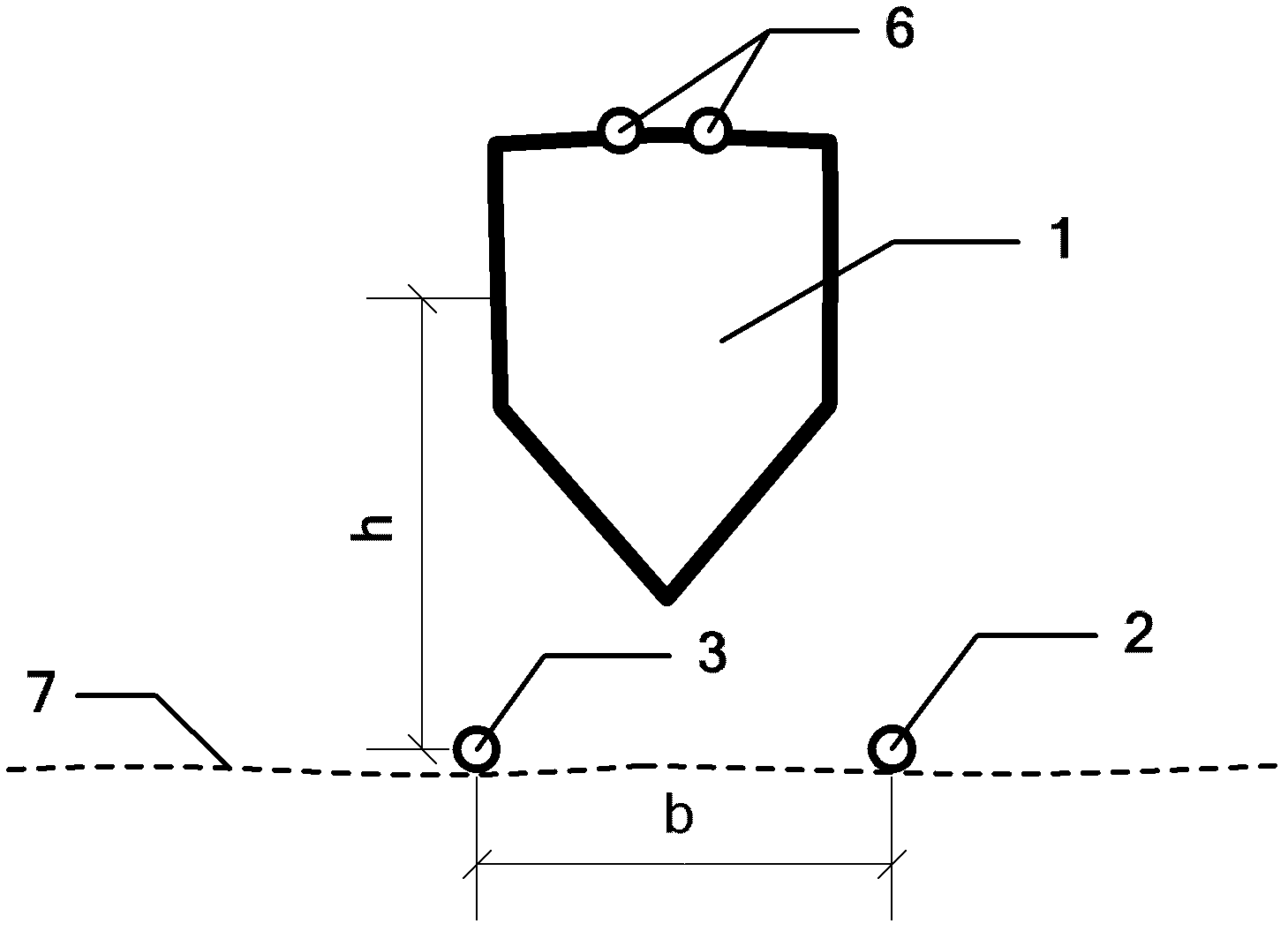
[0025] (1) Steps of laying submarine cables: such as figure 1 , figure 2 , image 3 As shown, the left submarine cable 3 and the right submarine cable 2 are laid in parallel along the geomagnetic east-west direction on the seabed 7 with a water depth of h=2B=3m, and the interval between the left and right submarine cables is b=2B=3m, which will be demagnetized Ship 1 is berthed above the left and right submarine cables, the axis of the degaussed ship is parallel to the left and right submarine cables, and the axis of the degaussed ship is projected on the seabed between the left and right submarine cables;
[0026] (2) Steps of forming a loop: use the left pulse power supply 5 and the right pulse power supply 4 to supply power to the left and right sub...
Embodiment 2
[0032] Example 2, a 2000-ton ship, ship width B=10m, midship radial circumference L=50m, vertical component of local geomagnetic field Hz=30A / m, Hp=20A / m, to achieve overall demagnetization , including the following steps:
[0033] (1) Steps of laying submarine cables: such as figure 1 , figure 2 , image 3 As shown, the left submarine cable 3 and the right submarine cable 2 are laid in parallel along the geomagnetic east-west direction on the seabed 7 with a water depth of h=1B=10m, and the interval between the left and right submarine cables is b=1B=10m, which will be demagnetized Ship 1 is berthed above the left and right submarine cables, the axis of the degaussed ship is parallel to the left and right submarine cables, and the axis of the degaussed ship is projected on the seabed between the left and right submarine cables;
[0034] (2) Steps of forming a loop: use the left pulse power supply 5 and the right pulse power supply 4 to supply power to the left and right s...
Embodiment 3
[0041] Example 3, a 30,000-ton ship, ship width B=30m, midship radial circumference L=100m, vertical component of local geomagnetic field Hz=20A / m, Hp=30A / m, to achieve overall demagnetization , including the following steps:
[0042] (1) Steps of laying submarine cables: such as figure 1 , figure 2 , image 3 As shown, the left submarine cable 3 and the right submarine cable 2 are laid in parallel along the geomagnetic east-west direction on the seabed 7 with a water depth of h=0.5B=15m, and the interval between the left and right submarine cables is b=0.5B=15m. The degaussed ship 1 is parked above the left and right submarine cables, the axis of the degaussed ship is parallel to the left and right submarine cables, and the degaussed ship axis is projected on the seabed between the left and right submarine cables;
[0043] (2) Steps of forming a loop: use the left pulse power supply 5 and the right pulse power supply 4 to supply power to the left and right submarine cable...
PUM
 Abstract
Description
Claims
Application Information
 - R&D
- Intellectual Property
- Life Sciences
- Materials
- Tech Scout
- Unparalleled Data Quality
- Higher Quality Content
- 60% Fewer Hallucinations
Browse by: Latest US Patents, China's latest patents, Technical Efficacy Thesaurus, Application Domain, Technology Topic, Popular Technical Reports.
© 2025 PatSnap. All rights reserved.Legal|Privacy policy|Modern Slavery Act Transparency Statement|Sitemap|About US| Contact US: help@patsnap.com


