
Deformation constraint optimization method for strength test wing

A constraint optimization and strength test technology, applied in multi-objective optimization, constraint-based CAD, aircraft component testing, etc., can solve the problems of complex follow-up loading structure, complex and different motion trajectories of loading points, and improve the accuracy of test loading Effect

Active Publication Date: 2020-08-04
CHINA AIRPLANT STRENGTH RES INST
View PDF4 Cites 4 Cited by
  • Summary
  • Abstract
  • Description
  • Claims
  • Application Information

AI Technical Summary

Problems solved by technology

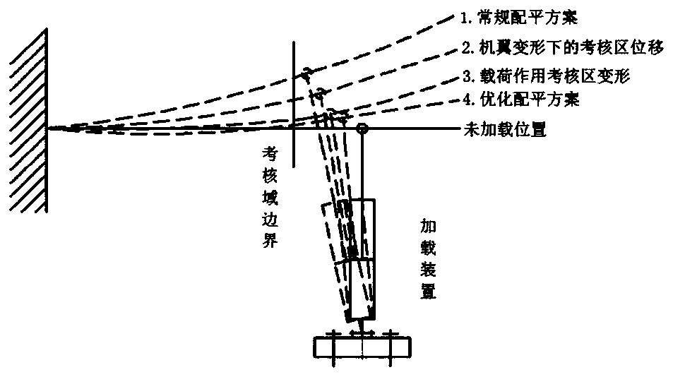
For the full-aircraft test of an amphibious aircraft, adding local restraints to the wings will cause super-static problems, which do not meet the relevant regulations of airworthiness and test standards; due to the particularity of the aircraft, the mission statement provided by the test client , it is clearly required that trim loads cannot be applied to the area from the assessment position to the wingtip; the structure of the buoy and the pressure-intensive large load determine that the follow-up loading structure is very complex, and the trajectory of each loading point is complex and different, which cannot be realized by the current follow-up loading technology

Method used


Image

  • Deformation constraint optimization method for strength test wing
  • Deformation constraint optimization method for strength test wing
  • Deformation constraint optimization method for strength test wing

Examples


Embodiment Construction

[0035] In order to make the objectives, technical solutions and advantages of the implementation of the application clearer, the technical solutions in the implementation modes of the application will be described in more detail below with reference to the drawings in the implementation modes of the application. In the drawings, the same or similar reference numerals denote the same or similar elements or elements having the same or similar functions throughout. The described embodiments are some, but not all, embodiments of the present application. The embodiments described below by referring to the figures are exemplary and are intended to explain the present application, and should not be construed as limiting the present application. Based on the implementation manners in this application, all other implementation manners obtained by persons of ordinary skill in the art without creative efforts fall within the scope of protection of this application. Embodiments of the pr...


PUM


Abstract

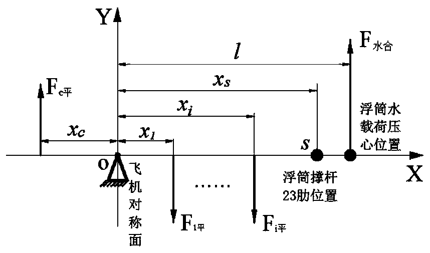
The invention belongs to the technical field of aircraft strength test design, and particularly relates to a deformation constraint optimization method for a strength test wing, which comprises the following steps: step 1, constructing a mechanical model of the test wing under the action of a water load, the mechanical model being a mechanical balance model of the wing under the action of the water load and a trimming load; 2, determining constraint conditions for deformation constraint optimization of the test wing according to the mechanical model; 3, converting multi-objective optimizationcontaining the two parameters into single-objective optimization based on the degree of influence of the deflection and the rotation angle on wing deformation by taking two optimization objectives ofthe minimum deflection and the minimum deflection angle at the boundary s of the area to be assessed as two optimization objectives; and 4, according to the constraint conditions in the step 2 and theoptimization target in the step 3, performing iterative solution by adopting an ant colony algorithm to obtain an optimal balancing load scheme. According to the invention, aircraft wing displacementand corner change caused by water load can be reduced at the same time, wing deformation is restrained, and the test loading precision is improved.

Description

technical field [0001] The application belongs to the technical field of aircraft strength testing, and in particular relates to a deformation constraint optimization method of a strength testing wing. Background technique [0002] When a large amphibious aircraft lands on water, the buoys and the hull structure of the fuselage will bear a huge water impact load. The water load has the characteristics of large magnitude, uniform distribution in the coverage area, and oblique ballast. Under the action of oblique ballast water load on the surface of the V-shaped structure of the buoy, the wing will have a significant upward displacement (the buoy is located below the wing and connected to the wing), resulting in a large deviation in the direction of the force line of the water load. Shift, load applied distortion. The compression stability of the water load loading device and the ability to adapt to angle changes are limited, which can easily cause the instability of the leve...

Claims


Application Information

Patent Timeline
IPC IPC(8): G06F30/15G06F30/17G06N3/00B64F5/60G06F111/06G06F111/04G06F119/14
CPCG06F30/15G06F30/17G06N3/006B64F5/60G06F2111/06G06F2111/04G06F2119/14Y02T90/00
Inventor 田文朋夏峰宋鹏飞张柁贺谦
Owner CHINA AIRPLANT STRENGTH RES INST
Learn More