
An optical fiber processing device

A processing device and optical fiber technology, applied in the field of optical fiber processing, can solve the problems of concentricity influence, concentricity deviation, improper installation of molds, etc., and achieve the effect of reducing concentricity errors, improving processing quality, and avoiding installation errors

Active Publication Date: 2020-09-29
JIANGSU HENGTONG OPTICAL FIBER TECH +2
View PDF0 Cites 0 Cited by
  • Summary
  • Abstract
  • Description
  • Claims
  • Application Information

AI Technical Summary

Problems solved by technology

However, when the personnel install the mold, the mold may not be installed in place, or the mold may have a slight deviation in the mold holder. When the 125 μm optical fiber passes through the mold, the coating of the optical fiber will appear uneven, thus Deviation of concentricity
In addition, when employees are installing the mold, the mold base will be subject to a certain force, and each time there are differences in direction and size, which will lead to a slight change in the position of the mold base, and will also affect the overall concentricity, resulting in Fiber processing quality is not stable

Method used


Image

  • An optical fiber processing device
  • An optical fiber processing device
  • An optical fiber processing device

Examples


Embodiment Construction

[0022] In the description of the present invention, it should be noted that the terms "center", "upper", "lower", "left", "right", "vertical", "horizontal", "inner", "outer" etc. The indicated orientation or positional relationship is based on the orientation or positional relationship shown in the drawings, and is only for the convenience of describing the present invention and simplifying the description, rather than indicating or implying that the referred device or element must have a specific orientation, or in a specific orientation. construction and operation, therefore, should not be construed as limiting the invention. In addition, the terms "first" and "second" are used for descriptive purposes only, and should not be understood as indicating or implying relative importance. Wherein, the terms "first position" and "second position" are two different positions.

[0023] Unless otherwise clearly specified and limited, the terms "mounted", "connected", "connected" and ...


PUM


Abstract

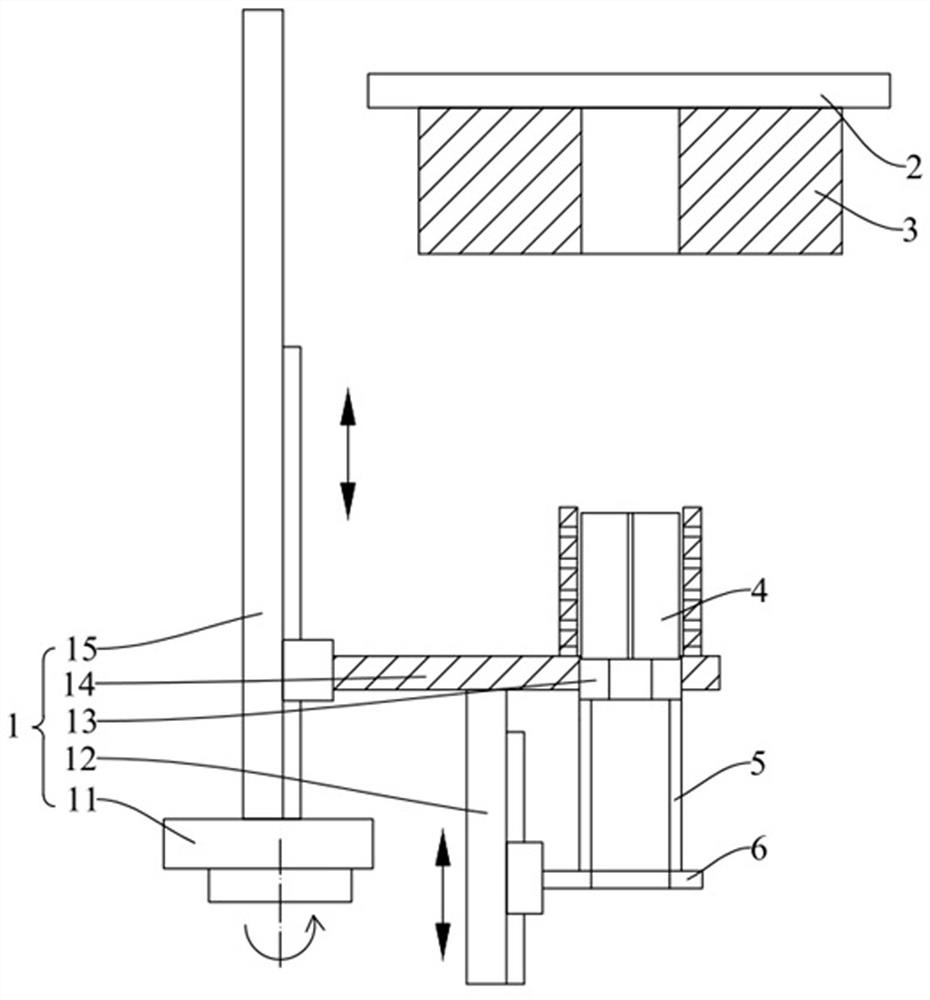
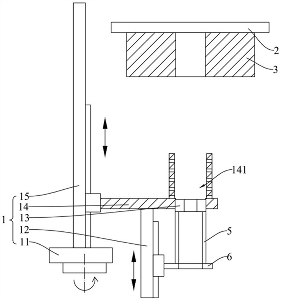
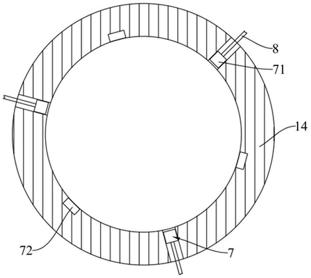
The invention discloses an optical fiber processing device, which belongs to the technical field of optical fiber processing. It includes a frame, a fine-tuning platform, a transfer mechanism, a first detection mechanism and a second detection mechanism. The fine-tuning platform is connected to the frame, and the fine-tuning platform is used to connect the mold base and can drive the mold base to move; the transfer mechanism is connected to the frame, and the transfer mechanism is used to push the mold set on the transfer mechanism into the installation hole; A detection mechanism is configured to obtain the position information of the installation hole, the first detection mechanism is connected to the transfer mechanism in communication, and the transfer mechanism can drive the mold to correspond to the position of the installation hole according to the position information of the installation hole; the second detection mechanism is arranged on the transfer mechanism The loading mechanism, the second detection mechanism is configured to obtain the position information of the optical fiber at the output end of the mold, the second detection mechanism is connected to the fine-tuning platform in communication, and the fine-tuning platform can drive the mold base to move along the diameter direction of the optical fiber according to the position information of the optical fiber. The invention can make the coating of the optical fiber uniform and improve the processing quality of the optical fiber.

Description

technical field [0001] The invention relates to the technical field of optical fiber processing, in particular to an optical fiber processing device. Background technique [0002] At present, the optical fiber market has higher and higher requirements for the quality of optical fibers. While considering the cost, major optical fiber manufacturers regard quality improvement as the top priority. [0003] Wet-on-wet coating is mainly used in optical fiber production. The coating mold adopting the wet-to-wet method includes an introduction mold, a primary coating mold, and a secondary coating mold. The three-section mold is directly loaded into the mold base as a whole. However, when the personnel install the mold, the mold may not be installed in place, or the mold may have a slight deviation in the mold holder. When the 125 μm optical fiber passes through the mold, the coating of the optical fiber will appear uneven, thus Concentricity deviation occurs. In addition, when em...

Claims


Application Information

Patent Timeline
Patent Type & Authority Patents(China)
IPC IPC(8): C03C25/12
CPCC03C25/12
Inventor 郝昌平陈伟严勇虎孙伟朱永刚韩泽五罗干周忠凯张功会卢萍曹少波陈进沈文华许明通顾灵卫
Owner JIANGSU HENGTONG OPTICAL FIBER TECH
Learn More