Steel component assembly method with supporting and positioning functions

An assembly method and technology of steel components, applied in the direction of auxiliary devices, auxiliary welding equipment, welding/cutting auxiliary equipment, etc., to achieve the effect of simple process, reducing assembly measures, and improving the utilization rate of cranes

Active Publication Date: 2020-08-04
中冶(上海)钢结构科技有限公司
View PDF7 Cites 0 Cited by
  • Summary
  • Abstract
  • Description
  • Claims
  • Application Information

AI Technical Summary

Problems solved by technology

The above-mentioned procedures are almost indispensable in the assembly of welded BH steel and the assembly of welded boxes.

Method used


Image

  • Steel component assembly method with supporting and positioning functions
  • Steel component assembly method with supporting and positioning functions

Examples


Embodiment Construction

[0015] The present invention is further illustrated below by specific examples.

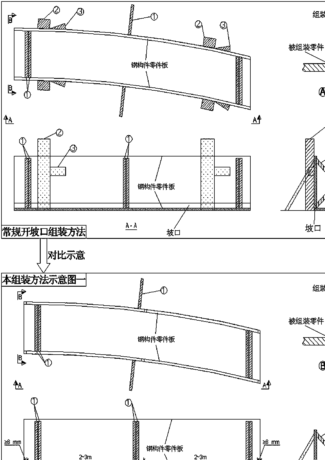
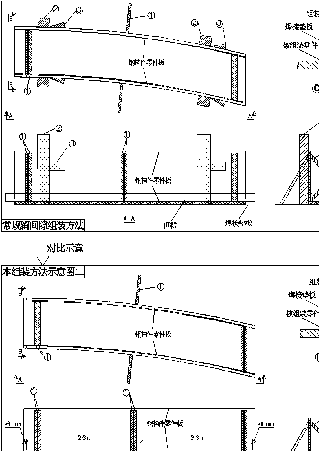
[0016] Such as Figure 1~Figure 2 As shown, a steel component assembly method with its own support and positioning functions;

[0017] Step 1. When cutting the groove or welding gap of the parts to be assembled, leave no less than 8mm long non-cut flanges at the two ends of the parts to be assembled and at a distance of 2~3m;

[0018] Step 2. When assembling the components, the non-cutting flange forms an effective stable contact surface. Further, forming a positioning line on the side of the non-cutting flange at both ends of the component parts also assists in the installation and positioning of the assembly parts. In this way, For the assembly of curved steel members to further increase its stability;

[0019] Step 3. Complete the pair assembly of the components. In this process, no additional use of abutment and wedges to repeatedly adjust the position is required, and the relative contact ...


PUM


Abstract

The invention specifically discloses a steel component assembly method with supporting and positioning functions. The steel component assembly method is characterized by comprising the following steps: leaving un-cut flanges with length not smaller than 8 mm on the two end heads of a part of a to-be-assembled part and positions every 2-3 m during groove cutting or gap welding for the part of the to-be-assembled part; defining an effective stable contact surface by the uncut flanges during component assembling, further defining positioning lines beside the un-cut flanges on the two end heads ofthe part of the component for assisting part mounting, positioning and assembling, thereby further improving stability of a bent steel component during bent steel component assembling; accomplishingcomponent assembling, and not repeatedly regulating the position by a backer and a wedge in the process. The method can precisely control the part mounting position by assembling the reserved flangesof the part, reduces fixing measures, simplifies the processes, shortens the assembly time, and effectively controls welding gaps among the part plates.

Description

technical field [0001] The invention relates to the field of steel structure assembly, in particular to a steel component assembly method with its own support and positioning functions. Background technique [0002] At present, in the assembly of steel components in the industry, in order to ensure verticality and positioning accuracy. Such as figure 1 As shown, when assembling, it is usually first to add the abutment of the assembly parts on the assembly tire frame, then hang the parts to the corresponding position and then add wedges to gradually adjust the verticality and positioning position of the parts. Add support welding to fix the parts on the side of the assembled parts, so that it is not easy to shift. The above-mentioned procedures are almost indispensable when assembling and welding the BH section steel and assembling and welding the box body. If the assembled parts need to be grooved or welded backing plates are added to leave welding gaps, the assembled par...

Claims


Application Information

Patent Timeline
IPC IPC(8): B23K37/04
CPCB23K37/04
Inventor 李章龙王伟张璐杨洋彭刚
Owner 中冶(上海)钢结构科技有限公司
Why Eureka
Try Eureka