
Synchronous auxiliary expiration device of air bag inflation and deflation type breathing machine

An inflatable and deflated, synchronous auxiliary technology, applied in the field of medical equipment, can solve the problem that the ventilator cannot provide the user with expiratory power

Inactive Publication Date: 2020-08-04
杨建新
View PDF6 Cites 1 Cited by
  • Summary
  • Abstract
  • Description
  • Claims
  • Application Information

AI Technical Summary

Problems solved by technology

[0005] The purpose of the present invention is to provide a synchronous auxiliary exhalation device for an air bag inflatable and deflated ventilator to solve the problem that the existing ventilator cannot provide the user with expiratory power

Method used


Image

  • Synchronous auxiliary expiration device of air bag inflation and deflation type breathing machine
  • Synchronous auxiliary expiration device of air bag inflation and deflation type breathing machine

Examples


Embodiment 1

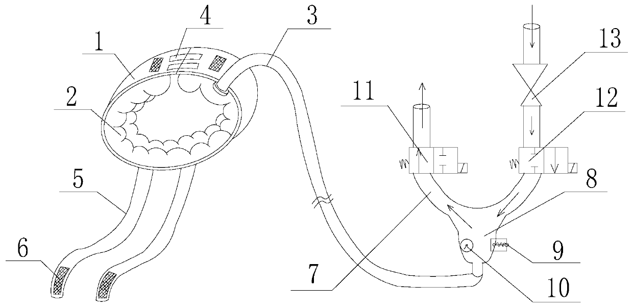
[0052] Such as figure 1 As shown, the airbag inflatable and deflated ventilator synchronous assisted exhalation device includes a device body, and the device body includes a bust sheath and a Y-shaped tee pipe 7, and between the bust sheath and the Y-shaped tee pipe 7 Connected through the connecting pipe 3;

[0053] The bust sheath includes a fabric layer 1, the fabric layer 1 is made of double-layer cotton canvas, the fabric layer has a certain degree of softness and no stretchability or slight stretchability, and the fabric layer 1 is a strip structure , the two ends of the strip structure are detachably connected by a connecting piece 4, the connecting piece 4 is a buckle, the inner side of the fabric layer 1 is provided with an airbag 2; the connecting pipe 3 is a flexible transparent plastic thread Tube.

[0054] The lower end pipeline of the Y-shaped three-way pipe 7 communicates with the air bag 2 through the connecting pipe 3, and the other two pipelines of the Y-s...

Embodiment 2

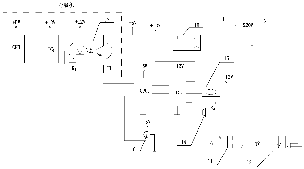
[0058] Such as figure 1 , figure 2 As shown, this embodiment is based on Embodiment 1, and also includes a control system for controlling the synchronization of the auxiliary exhalation device and the ventilator, and the control system includes a second central processing unit CPU 2 , the second backdriver IC 2 and relay 16;

[0059] The second central processing unit CPU 2 The input end of the ventilator is electrically connected with the output end of the optocoupler 17 of the ventilator, and the second central processing unit CPU 2 output of the second backdriver IC with the 2 The input terminal is electrically connected to the second backdriver IC 2 The output terminal is electrically connected to the input terminal of the relay 16, and the output terminal of the relay 16 is electrically connected to the two-position two normally closed solenoid valve 12 and the two-position two normally open solenoid valve 11.

[0060] The working principle of this embodiment:

[...

Embodiment 3

[0063] Such as figure 1 , figure 2 As shown, the present embodiment is based on embodiment 2, and the control system also includes a safety valve 9 and a second central processing unit CPU 2 An electrically connected pressure sensor 10; the three pipeline confluences of the Y-shaped tee pipe 7 expand to form an air chamber 8, and the safety valve 9 and the pressure sensor 10 are arranged in the air chamber 8; the control system also includes with the second central processing unit CPU 2 Electrically connected display 15 and alarm 14; the control system also includes a pressure relief valve 13, which is connected in series on the inflation pipeline; the relay 16 is a non-contact relay.


PUM


Abstract

The invention discloses a synchronous auxiliary expiration device of an air bag inflation and deflation type breathing machine. The device comprises a device body; the device body comprises a chest circumference sheath and a Y-shaped three-way pipe; the chest circumference sheath comprises a fabric layer which is made of a flexible material, and the flexible material has no flexibility or only hasmicro-flexibility; an air bag is arranged on the inner side of the fabric layer; a pipeline at the lower end of the Y-shaped three-way pipe is communicated with the air bag through a connecting pipe;the other two pipelines of the Y-shaped three-way pipe are respectively an inflation pipeline and an exhaust pipeline; the inflation pipeline is communicated with an inflation source; a two-positiontwo-way normally-closed electromagnetic valve and a two-position two-way normally-open electromagnetic valve are respectively arranged on the inflation pipeline and the exhaust pipeline; and power supply connecting wires of the two-position two-way normally-closed electromagnetic valve and the two-position two-way normally-open electromagnetic valve are connected in parallel in a same power supplycircuit and are controlled by a same relay. The breathing machine solves the problem that an existing breathing machine cannot provide power for expiration of a user.

Description

technical field [0001] The invention relates to the field of medical equipment, in particular to a synchronous auxiliary exhalation device for an air bag inflatable and deflated ventilator. Background technique [0002] Ventilators are commonly used and necessary medical equipment in critical care units (ICU wards) of hospitals at all levels. Ventilators have played an irreplaceable role in the treatment of critically ill patients. The working process of the existing ventilator is: when the ventilator is used to assist the patient to breathe or control the breathing, the whole breathing process is composed of breathing cycles one by one, and each breathing cycle is divided into an inspiratory phase and an expiratory phase. . In the inspiratory phase, the ventilator sends a certain amount of fresh gas rich in oxygen into the lungs of the patient through a certain pressure through the pipeline; in the exhaled phase, the gas containing carbon dioxide in the lungs is discharge...

Claims


Application Information

Patent Timeline
IPC IPC(8): A61M16/00A61H31/00
CPCA61M16/00A61M16/0003A61M16/0006A61H31/00A61H2031/003A61H2201/165A61M2205/18A61H2201/5056
Inventor 杨建新
Owner 杨建新
Learn More