
Cascading system, static voltage-sharing method and control device

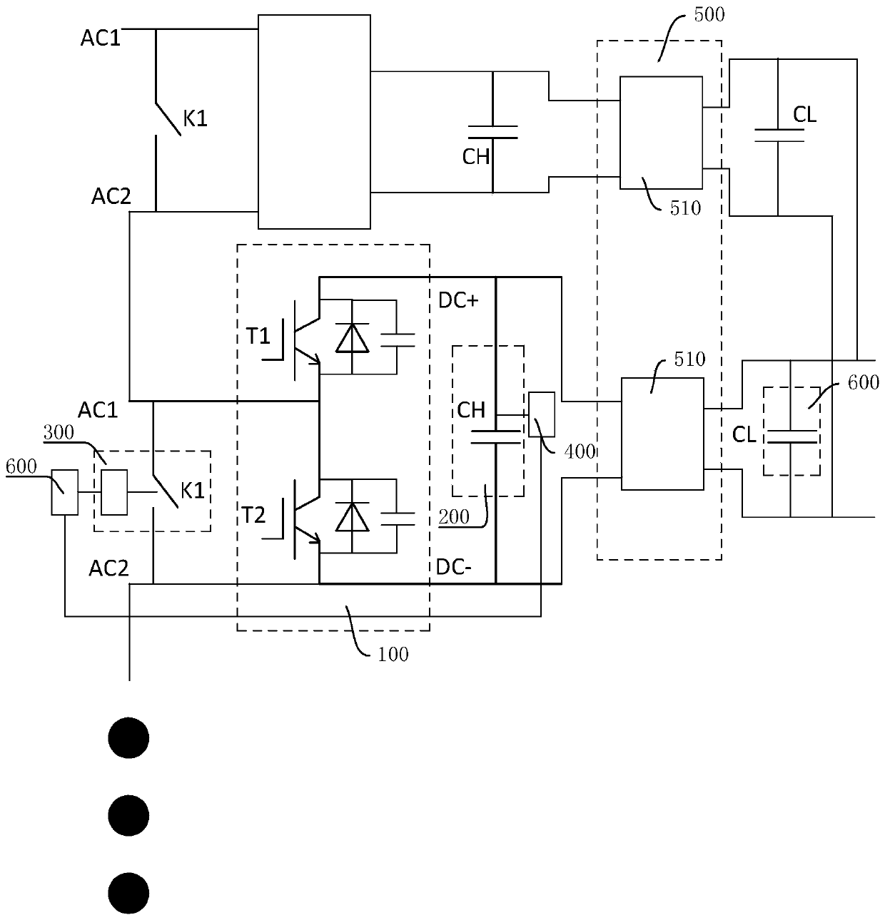
A cascade system, static technology, applied in the direction of output power conversion device, electrical components, irreversible DC power input conversion to AC power output, etc., can solve the problems of long-term use, damage to the first charging component, and power distribution Unequal problems, to achieve the effect of long-term hanging grid power supply standby, put into use, and improve the effect of static voltage equalization

Active Publication Date: 2020-07-31
GUANGDONG MINGYANG LONGYUAN POWER ELECTRONICS +1
View PDF5 Cites 0 Cited by
  • Summary
  • Abstract
  • Description
  • Claims
  • Application Information

AI Technical Summary

Problems solved by technology

[0003] However, after the cascade system is powered on and started, due to the lack of reasonable control over the charging of each power sub-module, it may cause uneven distribution of electric energy on each of the first charging components, which may eventually lead to a large loss of the first charging The power loss of the components is reduced to below the minimum power required by the external objects to obtain power, resulting in the loss of power of the external objects, the system fails and shuts down, or the first charging component with a small loss is kept charging, and the first charging component is damaged. Happening
[0004] In order to solve the above problems, the traditional voltage equalization method is to connect energy-discharging modules in parallel on the first charging components of each power sub-module, and the energy-discharging modules can be formed by connecting multiple energy-discharging components (such as resistors) in parallel, and each The parallel branches of each energy-dissipating component are provided with switching components. When the electric energy reserve of the first charging component of a certain power sub-module is relatively high, the switching components of more parallel-connected branches in the energy-dissipating module are closed at this time. Make more energy-dissipating components put into use, consume the electric energy on the first charging assembly, and for the situation that the electric energy reserve of the first charging assembly is low, then relatively reduce the closing of the switching components of the parallel branch in the energy-discharging module, thereby Cut off the number of energy-dissipating components to reduce the loss of the first charging component. However, this method consumes a lot of power for the entire system. Although it can stabilize the power of each first charging component within a certain range to a certain extent, it still cannot achieve long-term use, there is still a risk of power failure

Method used


Image

  • Cascading system, static voltage-sharing method and control device
  • Cascading system, static voltage-sharing method and control device

Examples


Embodiment Construction

[0028] Embodiments of the present invention are described in detail below, examples of which are shown in the drawings, wherein the same or similar reference numerals designate the same or similar elements or elements having the same or similar functions throughout. The embodiments described below by referring to the figures are exemplary only for explaining the present invention and should not be construed as limiting the present invention.

[0029] In the description of the present invention, it should be understood that when referring to orientation descriptions, such as terms "upper", "lower", "front", "rear", "left", "right", "vertical", "horizontal" ", "top", "bottom", "inner", "outer" and other indicated orientations or positional relationships are based on the orientations or positional relationships shown in the drawings, and are only for the convenience of describing the present invention and simplifying the description, rather than indicating Or imply that the devic...


PUM


Abstract

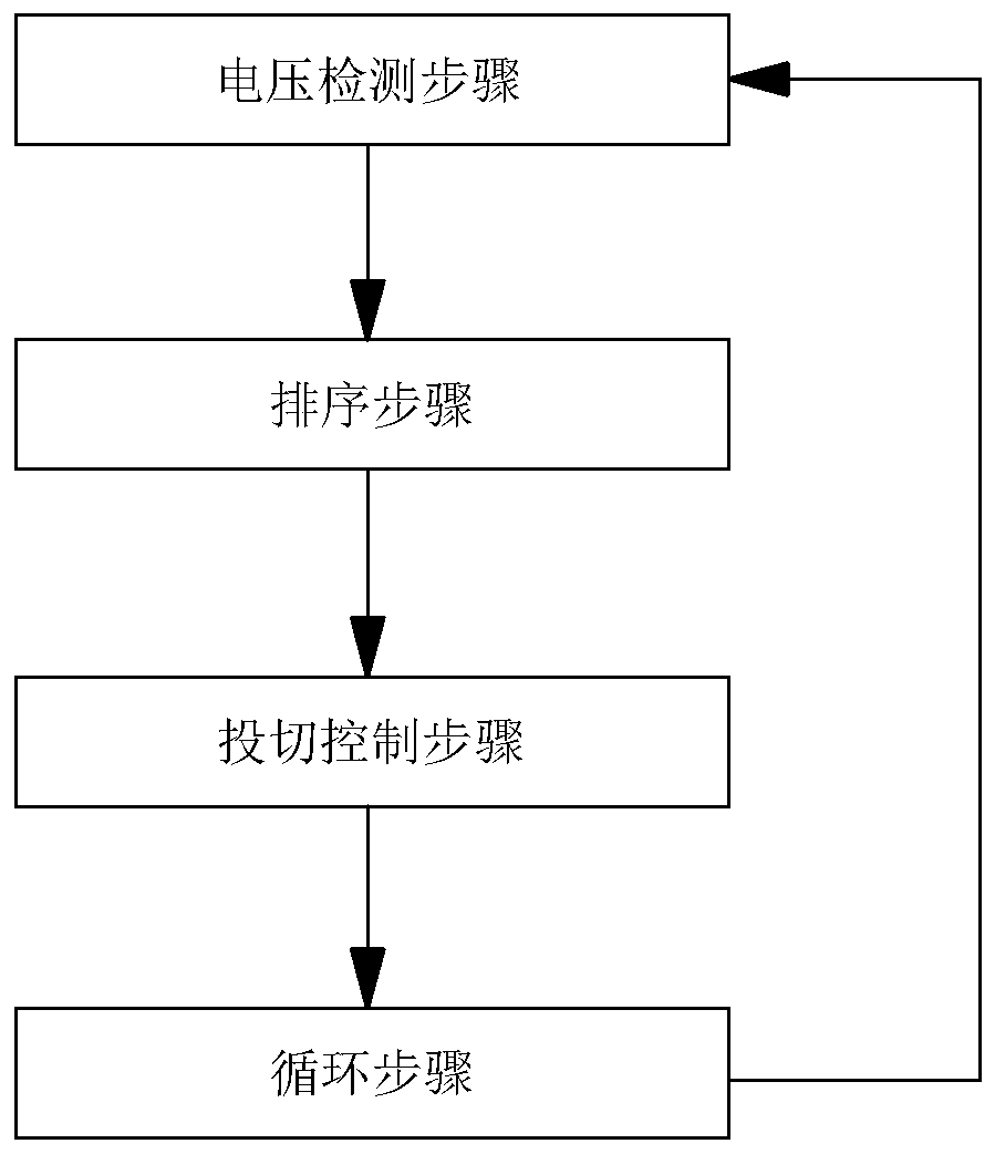
The invention discloses a cascade system, a static voltage-sharing method and a control device. The system comprises a power bridge arm, the power bridge arm comprises a plurality of power sub-modules. Each power sub-module is provided with a charging end and an input end; the input end of each power sub-module is connected with a bypass switch assembly in parallel. The charging end of each powersub-module is connected with a first charging assembly in parallel, and each power sub-module is provided with a voltage detection module used for detecting the charging condition of the first charging assembly. The input ends of the plurality of power sub-modules are sequentially connected in series; the charging end of the power sub-module can supply power to an external object, the bypass switch assembly can be switched on or switched off according to a detection signal of the voltage detection module, the cost can be reduced, the reliability can be improved, the static voltage-sharing effect of the power sub-module can be remarkably improved, and the system can stably supply power and operate.

Description

technical field [0001] The invention relates to the field of power electronics, in particular to a cascade system, a static voltage equalization method, and a control device. Background technique [0002] The traditional cascade system is composed of multiple power bridge arms, and the power bridge arm is composed of the input terminals of multiple power sub-modules in series, and then the two ends of the power bridge arm are respectively connected to the positive and negative poles of DC power, each The charging terminals of each power sub-module will be connected in parallel with the first charging component (such as a charging capacitor). When the power sub-module is put into operation, the charging terminal of the power sub-module will charge the first charging component. Objects (such as the control board of the system, etc.) supply power. [0003] However, after the cascade system is powered on and started, due to the lack of reasonable control over the charging of ea...

Claims


Application Information

Patent Timeline
Patent Type & Authority Applications(China)
IPC IPC(8): H02J3/18H02M7/48H02M1/32
CPCH02J3/18H02M7/48H02M1/32H02M1/007Y02E40/30
Inventor 彭国平宋海军史奔王红占王鹏博李杰杰张佩刚白代兵刘会民周治国徐元龙
Owner GUANGDONG MINGYANG LONGYUAN POWER ELECTRONICS
Learn More