
Electromagnetic clutch and clutch assembly

An electromagnetic clutch and clutch part technology, applied in the field of clutches, can solve the problems of large current, long cycle, high manufacturing cost, etc.

Pending Publication Date: 2020-07-31
QINGDAO DELIFENG MACHINERY
View PDF2 Cites 1 Cited by
  • Summary
  • Abstract
  • Description
  • Claims
  • Application Information

AI Technical Summary

Problems solved by technology

[0008] The object of the present invention is to provide an electromagnetic clutch and a clutch assembly to solve the problems of the prior art that the plane friction electromagnetic clutch has large current, high energy consumption and high failure rate, and the torsion spring electromagnetic clutch has complex structure, high manufacturing cost and long cycle time. , the technical problems of wedge-type electromagnetic clutch with complex structure, high process requirements and high manufacturing cost

Method used


Image

  • Electromagnetic clutch and clutch assembly
  • Electromagnetic clutch and clutch assembly
  • Electromagnetic clutch and clutch assembly

Examples


Embodiment Construction

[0040] In order to make the purpose, technical solution and advantages of the present invention clearer, the technical solution of the present invention will be described in detail below. Apparently, the described embodiments are only some of the embodiments of the present invention, but not all of them. Based on the embodiments of the present invention, all other implementations obtained by persons of ordinary skill in the art without making creative efforts fall within the protection scope of the present invention.

[0041] The purpose of this specific embodiment is to provide an electromagnetic clutch and clutch assembly to solve the problem of large current, high energy consumption and high failure rate of the plane friction electromagnetic clutch in the prior art, complex structure and high manufacturing cost of the torsion spring electromagnetic clutch. The cycle is long, the structure of the wedge electromagnetic clutch is complex, the process requirements are high, and...


PUM


Abstract

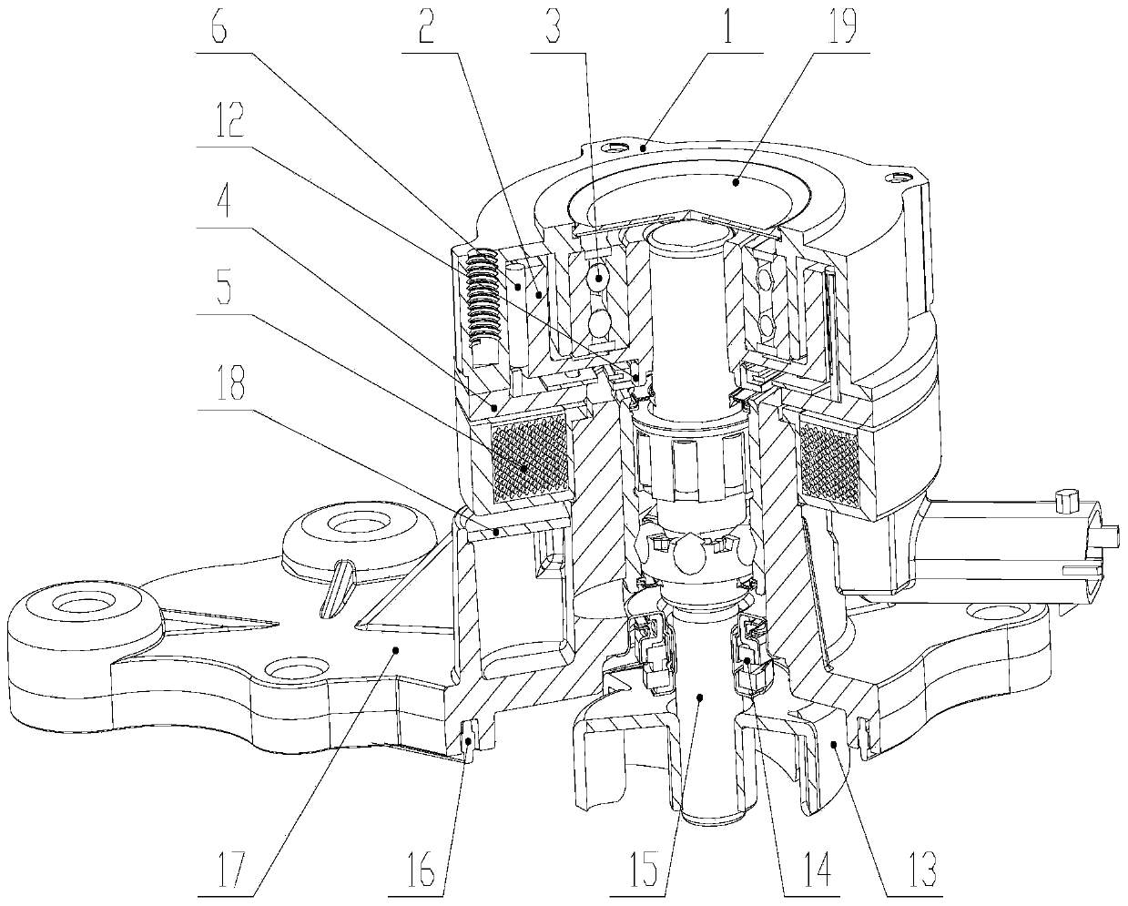
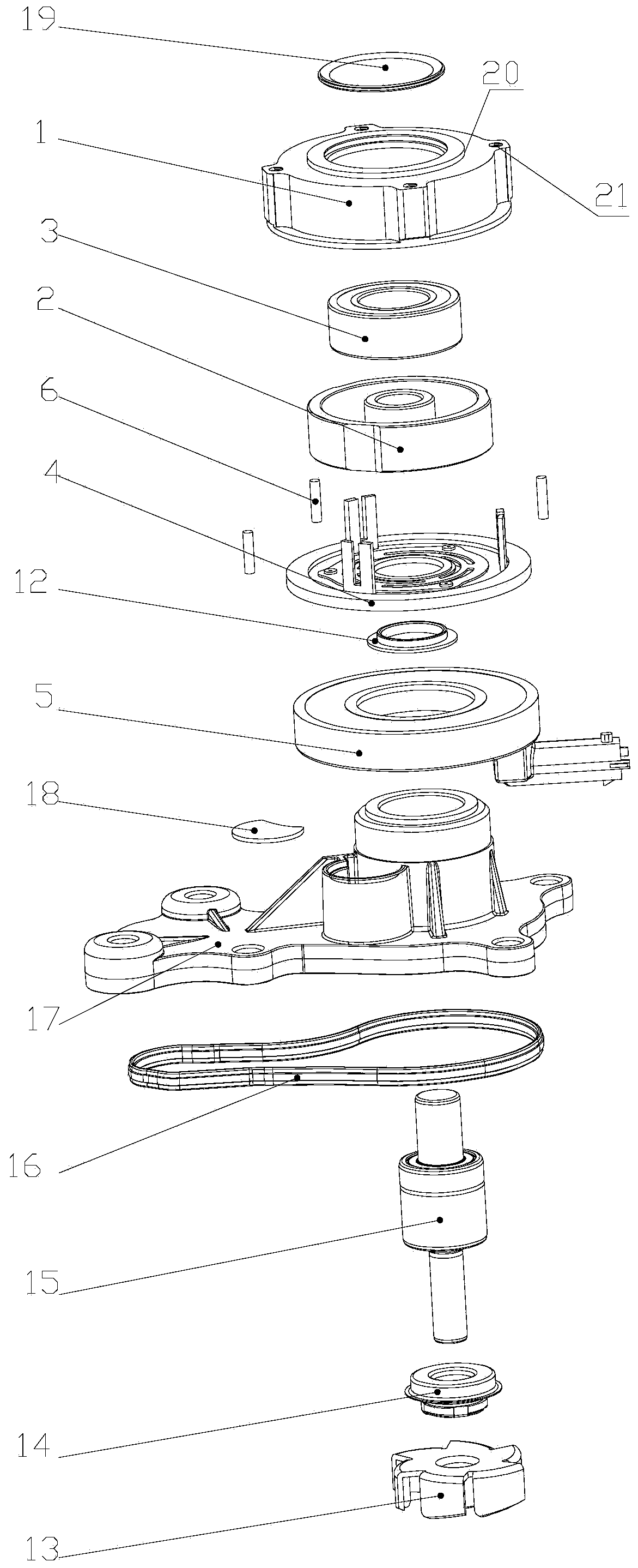
The invention discloses an electromagnetic clutch and a clutch assembly, and relates to the technical field of clutches. The electromagnetic clutch comprises a driving rotating clutch part, a driven rotating clutch part, a clutch bearing, an electrifying coil, an armature and a clamping piece, wherein the driving rotating clutch part and the driven rotating clutch part are rotatably arranged alonga first rotating center shaft; the clutch bearing is arranged between the driving rotating clutch part and the driven rotating clutch part, and a gap is formed between the driving rotating clutch part and the driven rotating clutch part; and the armature is rotatably arranged around the first rotating center shaft, and the clamping piece is arranged in the gap and is fixedly connected with the armature. According to the electromagnetic clutch and the clutch assembly, when the electrifying coil is not electrified, the upper end surface of the armature is pressed on the driving rotating clutchpart, the clamping piece is clamped in the gap, and the driving rotating clutch part, the driven rotating clutch part, the clamping piece and the armature synchronously rotate; and when the electrifying coil is electrified, the electrifying coil attracts the armature to move, the armature and the electrifying coil are attracted, meanwhile, the friction force between the clamping piece and the driving rotating clutch part is reduced, and the armature, the clamping piece and the driven rotating clutch part stop rotating.

Description

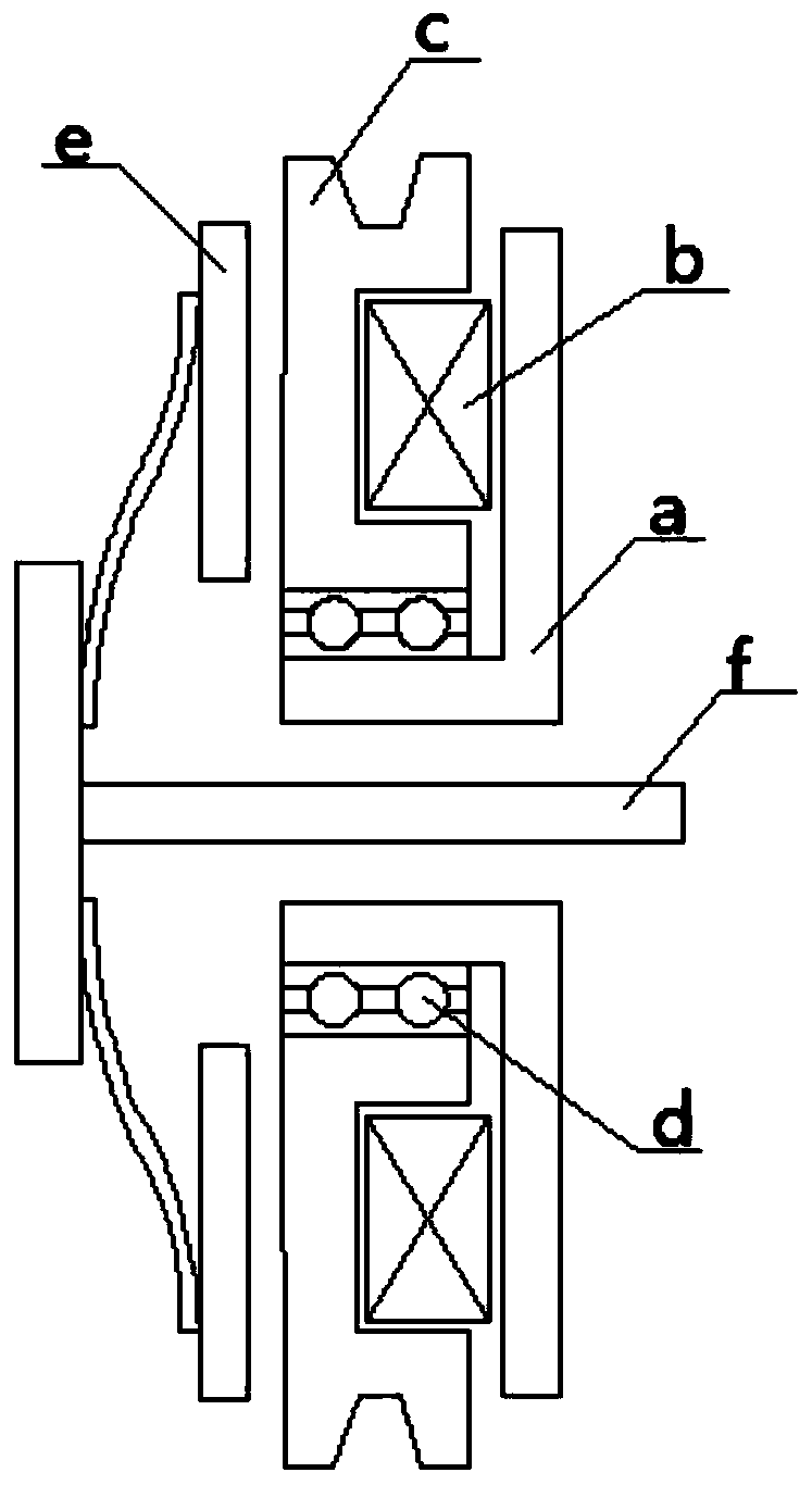
technical field [0001] The invention relates to the technical field of clutches, in particular to an electromagnetic clutch and a clutch assembly. Background technique [0002] Electromagnetic clutch is to control the combination and separation of clutch by using the electrification of electromagnetic coil, so as to realize the transmission and interruption of power. Electromagnetic clutch is widely used in mechanical, electrical and electronic fields, such as automobile water pump, air conditioning compressor, vacuum pump, etc. [0003] Electromagnetic clutches include three forms: plane friction type, torsion spring type and wedge type. [0004] Among them, the plane friction electromagnetic clutch is usually used in the air conditioner compressor, and whether the air conditioner compressor starts to work is controlled by the electromagnetic clutch at the front end of the compressor. Such as figure 1 As shown, the pulley c is in a state of continuous rotation, and the pu...

Claims


Application Information

Patent Timeline
IPC IPC(8): F16D27/07F16D27/14F01P7/16
CPCF01P7/162F16D27/06F16D27/14
Inventor 孙国栋
Owner QINGDAO DELIFENG MACHINERY
Learn More