Eureka AIR delivers breakthrough ideas for toughest innovation challenges, trusted by R&D personnel around the world.

Coal mine robot rail system and its omnidirectional deformation connection structure

A connecting structure and robot technology, applied in the track field, can solve the problems of heavy workload, difficulty in repairing and maintaining curved track, etc., and achieve the effect of smooth and smooth walking track.

Active Publication Date: 2021-08-10
TIANJIN HUANING ELECTRONICS
View PDF16 Cites 0 Cited by
  • Summary
  • Abstract
  • Description
  • Claims
  • Application Information

AI Technical Summary

Problems solved by technology

[0002] Rail technology plays an important role in various transportation links in industrial and mining enterprises. Conventional rails are mostly rigid bodies, and most of them are straight rails or curved rails with fixed shapes. Bending is made by bending a straight rail. The length and radian of the bend need to be surveyed and calculated in advance. In scenarios where the track lines are changeable such as mines, it is obviously a very large workload to form a fixed-shaped curved track by bending. Not only that, it is also more difficult to repair and maintain the curved track that is bent to form a fixed shape

Method used


Image

  • Coal mine robot rail system and its omnidirectional deformation connection structure
  • Coal mine robot rail system and its omnidirectional deformation connection structure
  • Coal mine robot rail system and its omnidirectional deformation connection structure

Examples


Embodiment 1

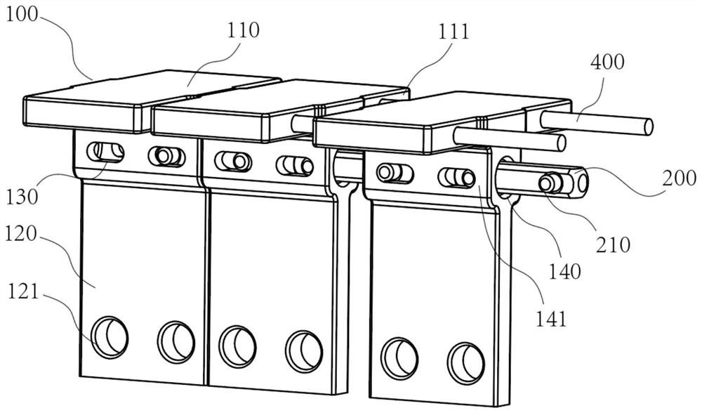
[0027] Such as figure 1 Shown is an implementation of a connection structure of the present invention, the connection between the support part 120 of the module unit 100 and the running part 110 is provided with a receiving hole 140 along the direction of the track, the connection member 200 is columnar, and its two ends are set In the receiving hole 140, the long hole 130 is arranged on the side walls on both sides of the receiving hole, and the limiting part 130 is a plug pin or a columnar part such as an expansion pin, and the connecting member 100 is vertically inserted into the long hole 130 on one side. The end of the connecting member 100 is extended into the long hole on the other side, and the end of the connecting member 100 is restricted in the receiving hole 140 .

[0028] In the embodiment of the present invention, the cross-sectional diameter of the limiting part 210 is slightly smaller than the width of the elongated hole 130, and at the same time, the maximum d...

Embodiment 2

[0035] Such as figure 2 The difference between the implementation of another connection structure of the present invention shown in Embodiment 1 is that the lower end of the support part 120 of the module unit is also provided with a second receiving hole 142, and the second receiving hole 142 of two adjacent module units A second connection member 201 is provided between the holes.

Embodiment 3

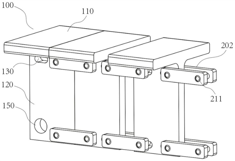
[0037] Such as image 3 The realization of another connecting structure of the present invention is shown, the connecting members shown are connecting pieces 202 arranged in pairs on both sides of two adjacent module units, and the ends of the connecting members 202 are placed on both sides of the elongated holes 130. On the side, the limiting part 211 connects the connecting members 202 on both sides through the long hole, so that a pair of connecting members are clamped on both sides of the module unit 100 .

[0038] In the embodiment of the present invention, the distance between the pair of connection members 202 is greater than the thickness of the module unit 100, so that there is a gap between the connection members and the module unit.

[0039] Preferably, the connecting members 202 are in two groups, which are respectively arranged at the upper and lower ends of the support part of the modular unit.

[0040] Preferably, series ribs are also provided between the runni...


PUM


Abstract

The invention discloses a track system for a coal mine robot and its omnidirectional deformation connection structure. The connection structure includes a plurality of module units connected in series, and the module unit has a carrier running part and a support part perpendicular to the running part. , two adjacent modular units are connected by at least one set of connecting members, the modular units are provided with long holes extending along the track direction, and the two ends of the connecting members are connected with the long holes through limiting parts, so The end of the connecting member can slide in the transverse space provided by the long hole under the cooperation of the stopper, so that the distance between two adjacent module units can be adjusted; between the connecting member and the module unit and the There is a gap between the limiting component and the long hole. The advantages and beneficial effects of the present invention are: to realize the flexible connection between the tracks, to efficiently realize the laying of track lines curved in various directions and angles, and to make a smooth transition between two sections of straight tracks.

Description

technical field [0001] The invention belongs to the technical field of rails, and in particular relates to a rail system for a coal mine robot and an omnidirectional deformation connection structure thereof. Background technique [0002] Rail technology plays an important role in various transportation links in industrial and mining enterprises. Conventional rails are mostly rigid bodies, and most of them are straight rails or fixed-shaped curved rails. Bending is made by bending straight rails. The length and radian of the bends need to be surveyed and calculated in advance. In scenarios where the track lines are changeable such as mines, it is obviously a very large workload to form a fixed-shaped curved track by bending. Not only that, but it is also more difficult to repair and maintain the curved track that is bent to form a fixed shape. Contents of the invention [0003] The purpose of the present invention is to overcome the defects in the prior art, provide a trac...

Claims


Application Information

Patent Timeline
Patent Type & Authority Patents(China)
IPC IPC(8): E01B23/02E01B23/04
CPCE01B23/02E01B23/04
Inventor 郑金文张远张德龙李克然
Owner TIANJIN HUANING ELECTRONICS
Why Eureka
Eureka Blog
Learn More