
Magnetic type flexible roller-fitting jig

A flexible and roll-on technology, which is applied to home appliances, other home appliances, flat products, etc., can solve problems such as the inability to adjust according to actual conditions, the bonding of different films is not tight enough, and the lack of flexibility of bonding fixtures, etc., to achieve The effect of increasing the scope of use, easy processing, and improving flexibility

Pending Publication Date: 2020-07-31
深圳市炎瑞自动化科技有限公司
View PDF0 Cites 0 Cited by
  • Summary
  • Abstract
  • Description
  • Claims
  • Application Information

AI Technical Summary

Problems solved by technology

[0004] The purpose of the present invention is to provide a magnetic flexible rolling fixture to solve the above-mentioned background technology that the existing bonding equipment on the market can only bond simple surfaces such as planes and 2.5D curved surfaces. For other types of surface such as 3D curved surfaces The lamination of special-shaped surfaces is mostly unsatisfactory, and it is easy to cause the problem of air bubbles due to insufficient lamination between different films, especially when laminating inner concave surfaces. The main reason is mostly lamination There is a problem with the fitting fixture. Because the film materials of electronic products are different and the shape is different, this leads to the fact that the fitting fixture as a whole cannot fit the concave surface or the inner cavity well. In addition, the fixture cannot move in the cavity. , can not be adjusted according to the actual situation, which makes the overall lack of flexibility of the bonding fixture

Method used


Image

  • Magnetic type flexible roller-fitting jig
  • Magnetic type flexible roller-fitting jig
  • Magnetic type flexible roller-fitting jig

Examples


Embodiment Construction

[0023] The following will clearly and completely describe the technical solutions in the embodiments of the present invention with reference to the accompanying drawings in the embodiments of the present invention. Obviously, the described embodiments are only some, not all, embodiments of the present invention. Based on the embodiments of the present invention, all other embodiments obtained by persons of ordinary skill in the art without making creative efforts belong to the protection scope of the present invention.

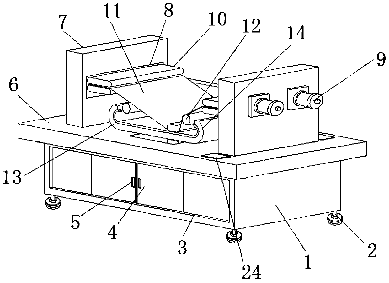
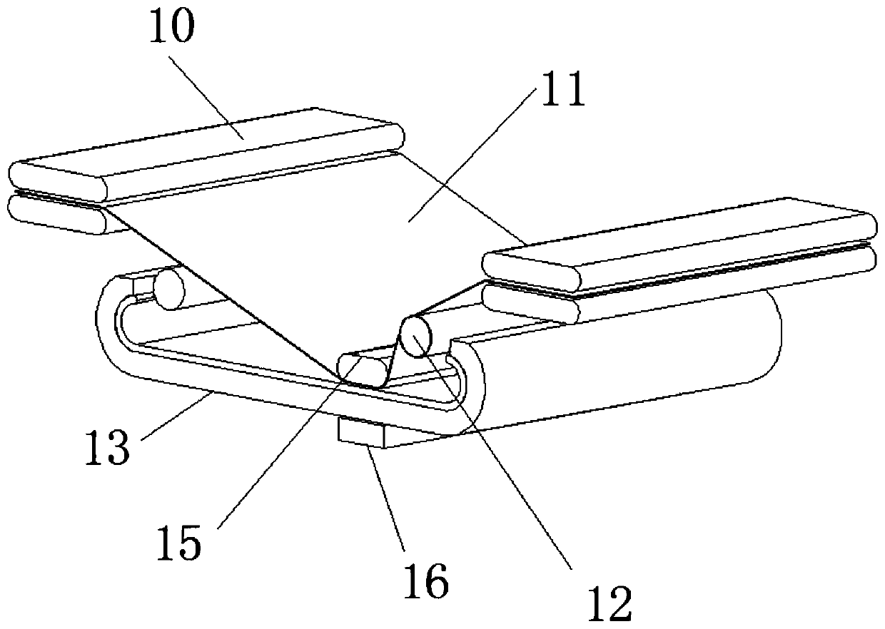
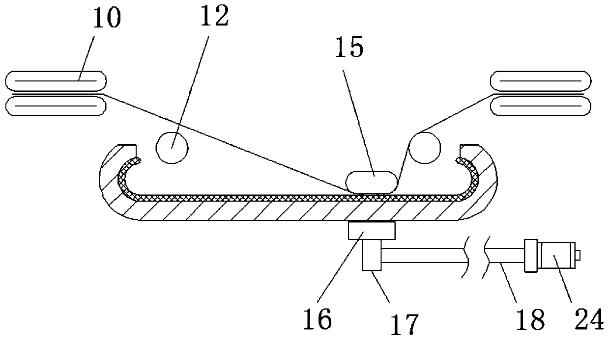
[0024] see Figure 1-6 , the present invention provides a technical solution: a magnetic flexible rolling fixture, including an equipment installation frame 1, the lower end of the equipment installation frame 1 is movably installed with adjustable feet 2, and the outside of the equipment installation frame 1 is provided with Positioning installation slot 3, a maintenance protective door 4 is movable installed in the positioning installation slot 3, a mobile h...


PUM


Abstract

The invention discloses a magnetic type flexible roller-fitting jig. The magnetic type flexible roller-fitting jig comprises an equipment mounting rack, wherein the lower end of the equipment mountingframe is movably equipped with adjustable supporting legs; the outer side of the equipment mounting rack is provided with a positioning mounting slot; a maintaining protective door is movably mountedin the positioning mounting slot; a movable pulling handle slot is formed in the outer side of the maintaining protective door; the upper end of the equipment mounting rack is fixedly equipped with aworking table board; the upper end of the working table board is fixedly equipped with a fixed mounting bracket; a positioning connecting slot is formed inside the fixed mounting bracket; the outer side of the fixed mounting bracket is fixedly equipped with a drive gas cylinder; a telescopic device is movably mounted in the positioning connecting slot; and a flexible connector is movably mountedin the telescopic device. The magnetic type flexible roller-fitting jig performs real-time regulating work on fitting pressure by regulating the size of movable magnetic fields at the lower end, meetsuse needs better, and makes flexibility degree of the whole device higher.

Description

technical field [0001] The invention relates to the technical field of lamination equipment, in particular to a magnetic flexible rolling lamination fixture. Background technique [0002] In recent years, with the advancement of science and technology, many electronic devices use touch display panels. Touch mobile phones, as the name implies, refer to mobile phones that support full touch screens, which can realize functions such as full-screen drag and drop. Generally speaking, touch The control display panel includes a touch module, which is made of multi-layer film. The film is a thin and soft transparent sheet made of plastic, adhesive, rubber or other materials. The scientific explanation of the film is: A 2-dimensional material formed by depositing atoms, molecules or ions on the surface of a substrate, interference generated by a thin film, which can be a transparent solid, liquid or a thin layer of gas sandwiched by two pieces of glass, the incident light is reflecte...

Claims


Application Information

Patent Timeline
Patent Type & Authority Applications(China)
IPC IPC(8): B29C65/56B29C65/78B29L7/00
CPCB29C65/56B29C66/45B29C65/7802B29C66/83411B29C66/8244B29C66/87B29L2007/00
Inventor 杨越猛
Owner 深圳市炎瑞自动化科技有限公司
Learn More