Eureka AIR delivers breakthrough ideas for toughest innovation challenges, trusted by R&D personnel around the world.

Generator set assembly stand and use method thereof

A technology for generator sets and benches, which is applied to workbenches, workpiece clamping devices, manufacturing tools, etc. It can solve the problems of inconvenient height adjustment of assembly benches and failure of generator clamping, etc., and achieves simple structure and convenient height adjustment , strong practical effect

Pending Publication Date: 2020-07-28
HEFEI CALSIION ELECTRIC POWER SYST
View PDF7 Cites 2 Cited by
  • Summary
  • Abstract
  • Description
  • Claims
  • Application Information

AI Technical Summary

Problems solved by technology

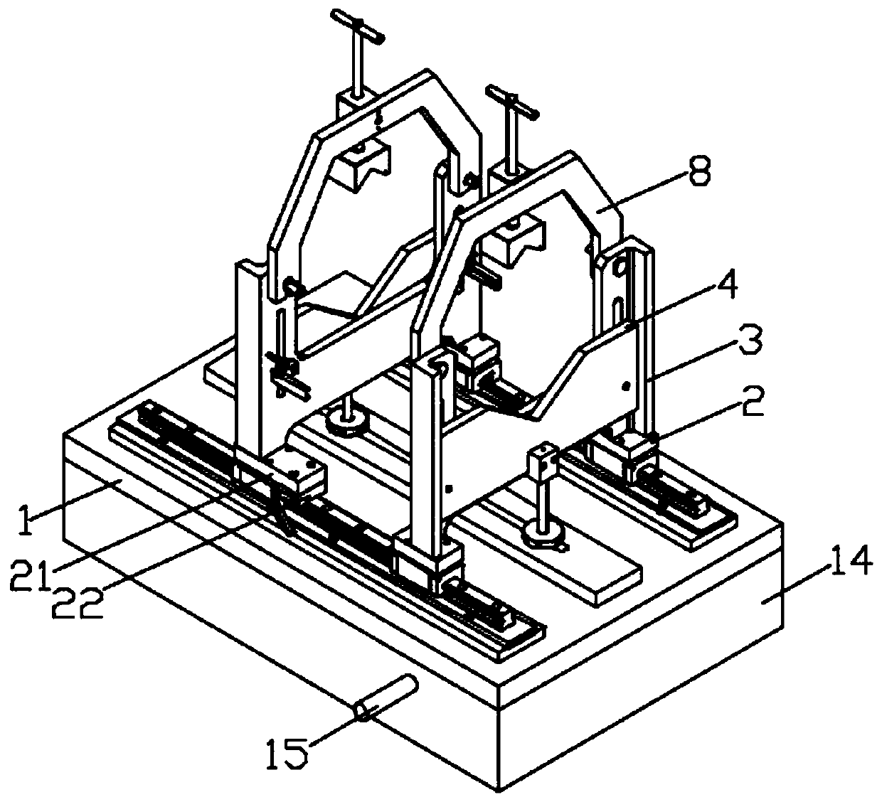
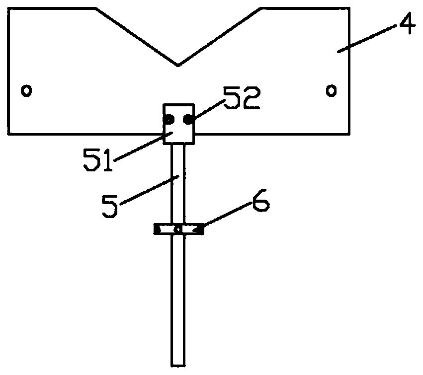
[0004] The object of the present invention is to provide a generator set assembly stand and its use method to solve the following technical problems: (1) By rotating the first drive rod, the first drive rod drives the second drive rod to rotate through the pulley, and at the same time the first drive The first rod sleeve on the rod drives the third rod sleeve to rotate through the transmission belt, the second rod sleeve on the second driving rod drives the fourth rod sleeve to rotate through the transmission belt, and then drives the support column to lift through the clamping block to complete the stand The height adjustment of the main body, through the above structure, makes the height adjustment of the genset assembly stand more convenient, facilitates the use of operators of different heights, meets the needs of different heights, and solves the inconvenient height adjustment of the genset assembly stand in the prior art (2) Put the generator set on the fixed plate, push the two moving frames along the direction of the slide rail, the moving frame drives the fixed block and the rotating block to move, rotate the third screw, and the third screw drives the rotating pin to rotate , and then drive the rotating block and the fixed block to rotate, the fixed block and the rotating block contact the corner of the generator set after rotating, and then rotate the second fastening sleeve to lock the third screw, and the rotating block and the fixed block are fixed. , so that the generator set assembly platform can effectively fix and clamp the generator set, and at the same time, the rotating block and the fixed block can meet the clamping of corners of different shapes of the generator set, solving the problem that the generator set assembly platform in the prior art cannot The technical problem of effective clamping of the generator in the process; (3) by rotating the second screw rod, the second screw rod cooperates with the screw rod seat to move downward, and the second screw rod pushes down the limit block, and the limit block is opposite to the The top of the generator set is limited. When the generator set needs to be lifted, turn the second screw to move the limit block to the top, push the lifting plate upward, and the lifting plate drives the fixed block up through the fixed pin, and then drives the clamped generator. The unit rises, and after lifting, turn the first fastening sleeve to fix the first screw rod, which solves the problem that the generator set assembly platform in the prior art cannot adjust the height of the generator set, which is inconvenient for subsequent assembly work

Method used


Image

  • Generator set assembly stand and use method thereof
  • Generator set assembly stand and use method thereof
  • Generator set assembly stand and use method thereof

Examples


Embodiment Construction

[0030] The following will clearly and completely describe the technical solutions in the embodiments of the present invention with reference to the accompanying drawings in the embodiments of the present invention. Obviously, the described embodiments are only some, not all, embodiments of the present invention. Based on the embodiments of the present invention, all other embodiments obtained by persons of ordinary skill in the art without creative efforts fall within the protection scope of the present invention.

[0031] see Figure 1-8As shown, the present invention is a generator set assembly platform, including a platform body 1, on which two mobile frames 3 are slidably arranged, and a mounting plate 8 is installed on the top of the mobile frame 3, and a mounting plate 8 is installed on the mounting plate 8. Screw base 81, screw base 81 rotates and connects second screw mandrel 82, the bottom of second screw mandrel 82 is equipped with limiting block 83, and lifting plat...


PUM


Abstract

The invention discloses a generator set assembly stand and a use method thereof. The generator set assembly stand includes a stand body, two movable frames are slidably arranged on the stand body, a mounting plate is installed at the top of each movable frame, and a screw rod seat is installed on each mounting plate. The screw rod seats are rotatably connected with second screw rods, and limitingblocks are installed at the bottoms of the second screw rods. By rotating a first driving rod, the first driving rod drives a second driving rod to rotate through a pulley, while a first rod sleeve onthe first driving rod drives a third rod sleeve to rotate through a transmission belt, a second rod sleeve on the second driving rod drives a fourth rod sleeve to rotate through a transmission belt,and then a supporting column is driven to lift and lower by a clamp block to complete the height adjustment of the stand body; and through the structure, the height adjustment of the generator set assembly stand is more convenient, operators with different heights can use conveniently, the requirements of different heights can be met, and the technical problem of inconvenient adjustment of the height of the generator set assembly stand in the prior art is solved.

Description

technical field [0001] The invention relates to the technical field of generator sets, in particular to a generator set assembly stand and a method for using the same. Background technique [0002] A generator is a mechanical device that converts other forms of energy into electrical energy. It is driven by a water turbine, steam turbine, diesel engine or other power machinery, and converts the energy generated by water flow, air flow, fuel combustion or nuclear fission into mechanical energy and transmits it to the generator. Converted to electrical energy by a generator. The generator set needs to be carried out on the assembly bench during the assembly process. [0003] The height adjustment of the existing generator set assembly platform is inconvenient and cannot meet the needs of operators of different heights and requirements for assembly. At the same time, the existing assembly platform has a complex structure and cannot clamp generator sets of different shapes duri...

Claims


Application Information

Patent Timeline
Patent Type & Authority Applications(China)
IPC IPC(8): B25H1/16B25B11/02B25H1/10B25B27/00
CPCB25H1/16B25B11/02B25H1/10B25B27/00
Inventor 邹国祥杜永辉
Owner HEFEI CALSIION ELECTRIC POWER SYST
Why Eureka
Eureka Blog
Learn More