Power box safe for use

A power box, safe technology, applied in electrical components, substation/switch layout details, substation/switchgear cooling/ventilation, etc., can solve the problems of unsafe use, easy unlocking, lock lever disengagement, etc., to improve the user experience Sensation, improve safety effect

Active Publication Date: 2020-07-24
浙江海得成套设备制造有限公司
View PDF10 Cites 2 Cited by
  • Summary
  • Abstract
  • Description
  • Claims
  • Application Information

AI Technical Summary

Problems solved by technology

[0002] The power box in the prior art generally includes a box body and a box door. The box body includes an outer box body and an inner box body. A heat-insulating cavity is formed between the outer box body and the inner box body. A handle is provided on the front of the box door. The left side of the box is movably connected to the left side of the inner box through a hinge, and the right side of the box door is provided with an inward connecting edge. After the box door is installed in place, the connecting edge touches the right side of the inner box, that is, the power box The connecting side realizes the installation and positioning of the box door, and the locking bar realizes the locking of the position of the connecting side, and then realizes the locking of the box door. However, in the actual use process, the locking bar is often misoperated and separated from the connecting side, resulting in unsafe use. , so it is urgent to optimize the locking structure of the box door to prevent the lock bar from being easily unlocked under the action of misoperation

Method used


Image

  • Power box safe for use
  • Power box safe for use

Examples


Embodiment Construction

[0017] The technical solution of this patent will be further described in detail below in conjunction with specific embodiments.

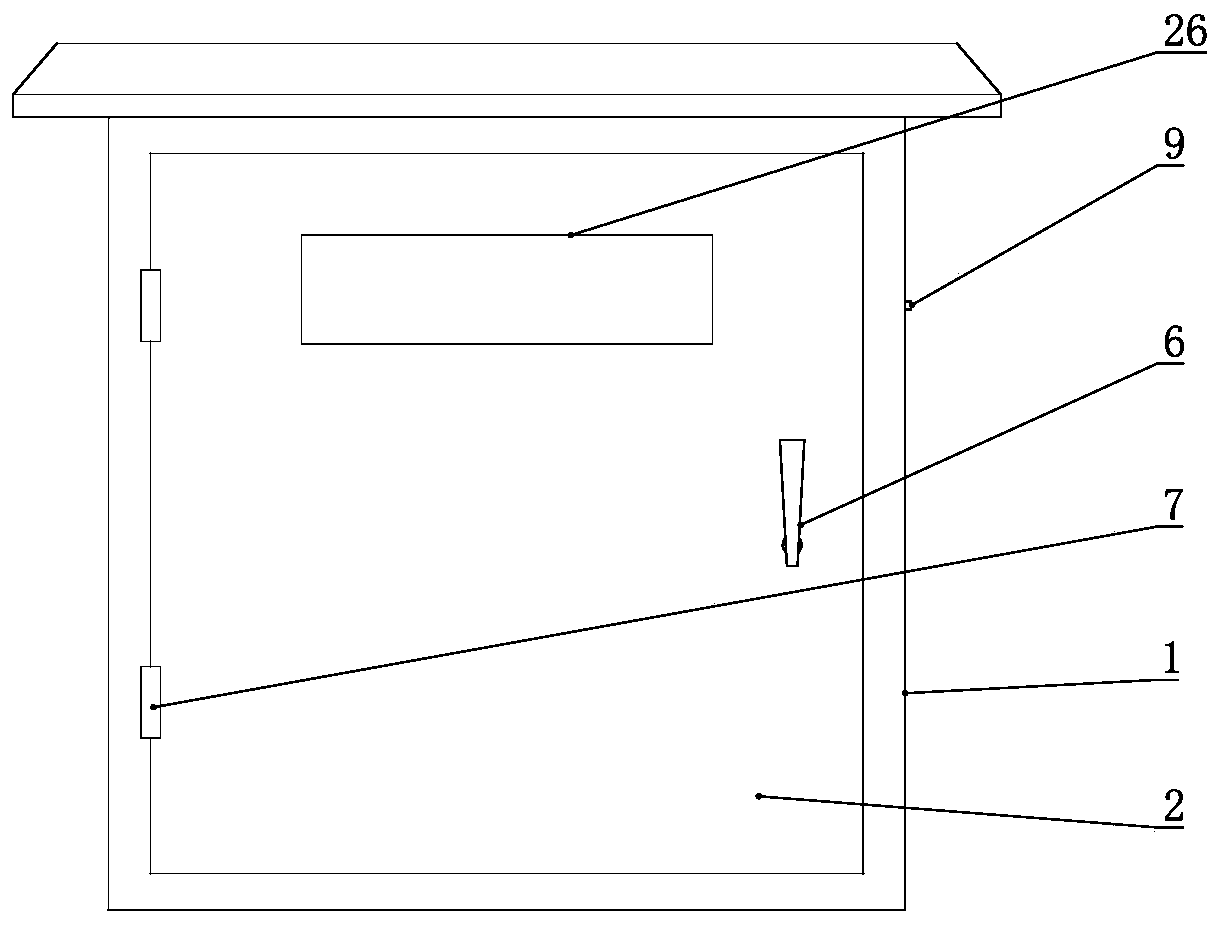
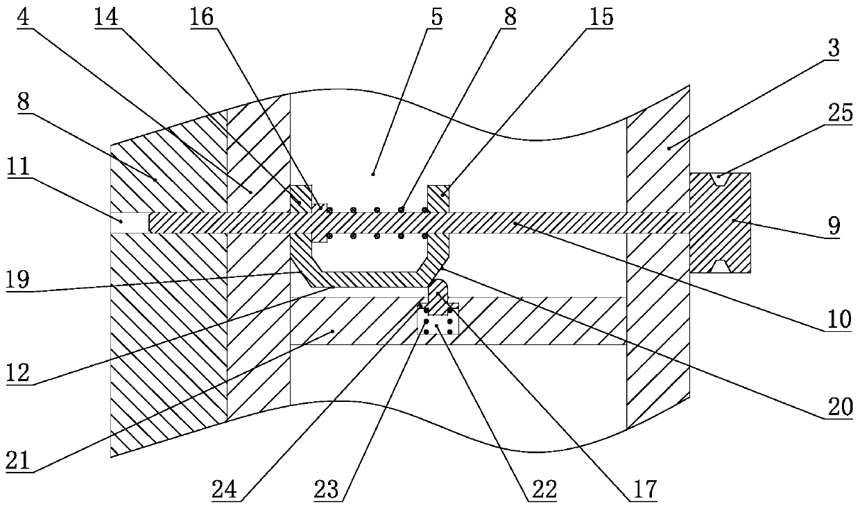
[0018] see Figure 1-Figure 2 , the safe power box in the embodiment of the present invention includes a box body 1 and a box door 2, the box body 1 includes an outer box body 3 and an inner box body 4, the inner box body 4 is used to place electrical devices, etc., and the outer box body 3 A heat-insulating cavity 5 is formed between the inner box body 4, so that the inner box body 4 is less affected by the temperature of the external link. The front of the box door 2 is provided with a handle 6, and the left side of the box door 2 is connected to the inner box through the hinge 7. The left side of the box body 4 is movably connected, and the right side of the box door 2 is provided with an inward connecting edge 8, which is formed by turning the right side of the box door 2 inward. After the box door 2 is installed in place, the connecting edge 8...


PUM


Abstract

The invention discloses a power box safe for use. The box comprises a box body and a box door, wherein the box body includes an outer box body and an inner box body; a heat insulation cavity is formedbetween the outer box body and the inner box body; a handle is arranged on a front surface of the box door; a left side of the box door is movably connected with the left side of the inner box body through hinges; an inward connecting edge is arranged on a right side of the box door; after the box door is installed in place, the connecting edge abuts against the right side of the inner box body;a lock knob is arranged on the right side of the outer box body; the left side of the lock knob is connected with a lock rod; and a lock hole is formed in the connecting edge, the lock rod stretches into the lock hole of the connecting edge from the outer box body, the heat insulation cavity and the inner box body from left to right, the lock rod is provided with the one-way resistance assembly, the one-way resistance assembly forms resistance for preventing the lock rod from moving rightwards, in other words, the lock rod can move rightwards only through a large acting force, the lock rod isnot prone to unlocking, and use safety of a user is improved.

Description

technical field [0001] The invention relates to the field of electric power engineering, in particular to a safe electric box. Background technique [0002] The power box in the prior art generally includes a box body and a box door. The box body includes an outer box body and an inner box body. A heat-insulating cavity is formed between the outer box body and the inner box body. A handle is provided on the front of the box door. The left side of the box is movably connected to the left side of the inner box through a hinge, and the right side of the box door is provided with an inward connecting edge. After the box door is installed in place, the connecting edge touches the right side of the inner box, that is, the power box The connecting side realizes the installation and positioning of the box door, and the locking bar realizes the locking of the position of the connecting side, and then realizes the locking of the box door. However, in the actual use process, the lockin...

Claims


Application Information

Patent Timeline
Patent Type & Authority Applications(China)
IPC IPC(8): H02B1/56H02B1/48H02B1/46E05B65/52E05B15/00
CPCE05B15/00E05B65/5215H02B1/46H02B1/48H02B1/565
Inventor 徐冰李东
Owner 浙江海得成套设备制造有限公司
Why Eureka
Try Eureka