
Subcritical rod carving method using source range detector signal as signal source

A Source Range Detector, Subcritical Technology

Active Publication Date: 2020-07-24
NUCLEAR POWER INSTITUTE OF CHINA
View PDF6 Cites 5 Cited by
  • Summary
  • Abstract
  • Description
  • Claims
  • Application Information

AI Technical Summary

Problems solved by technology

[0025] The technical problem to be solved by the present invention is: the test process of the conventional subcritical rod marking method is complicated, the economic cost is relatively high in the implementation process, and the practicability is relatively poor. sub-cutting bar method

Method used


Image

  • Subcritical rod carving method using source range detector signal as signal source
  • Subcritical rod carving method using source range detector signal as signal source
  • Subcritical rod carving method using source range detector signal as signal source

Examples


Embodiment 1

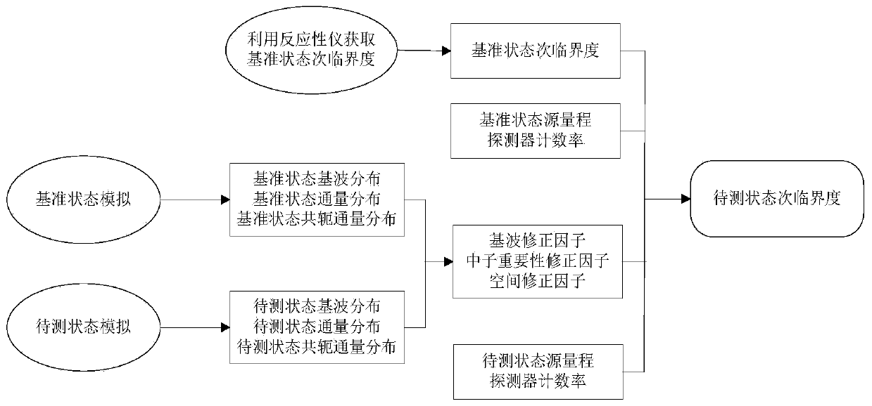
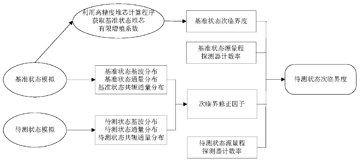
[0064] This embodiment provides a subcritical engraving method using the source range detector signal as the signal source, such as image 3 Shown: In the preparation stage of the subcritical indentation test, firstly through the reference state simulation, using the high-precision steady-state core calculation software that can fully consider the influence of external sources on the core neutron flux distribution in the subcritical state, calculate The finite multiplication coefficient of the core in the reference state is used to obtain the subcriticality of the core in the reference state, and generate key parameters including the fundamental wave distribution, flux distribution and conjugate flux distribution in the reference state; at the same time, each state to be tested can be performed The core simulation, using high-precision steady-state core calculation software that can fully consider the influence of external sources on the core neutron flux distribution in the subc...

Embodiment 2

[0086] As shown in Table 1 to Table 3, it is an embodiment of measuring the sub-criticality of the core in each rod state in the sub-criticality rod test of a certain group of control rods in a certain reactor according to the present invention.

[0087] Table 1 Source range detector count rate in each state

[0088]

[0089]

[0090] Table 2 Subcritical correction factor library prepared for two states to be tested

[0091] Core state Subcritical correction factor State to be tested 1#0.4500 State to be tested 2# 0.6085

[0092] Table 3 "Measurement" results of the finite multiplication coefficient of the core under test in the critical rod test

[0093]

[0094] Table 1 shows the count rate of the source range detector in each state, including the reference state and 2 states to be measured.

[0095] Table 2 is the subcritical correction factor library prepared for the two states to be tested in Table 1 before the subcritical bar test.

[0096] Table 3 shows the "measurement" res...


PUM


Abstract

The invention discloses a subcritical rod carving method using a source range detector signal as a signal source. The method can be used for measuring the value of the control rod when the reactor isin a deep subcritical state and comprises the steps: recording a neutron counting rate signal of the source range detector when a reactor core is in a to-be-detected state after a certain control rodgroup is lifted out of or inserted into the reactor core; calling a subcritical correction factor, correcting the neutron counting rate signal of the source range detector through the subcritical correction factor, then comparing the corrected signal with the counting rate and reactivity of the reference state source range detector, and finally obtaining the reactivity of the reactor core in eachto-be-measured state so as to complete rod carving. The economic cost can be effectively reduced while the measurement precision is guaranteed.

Description

Technical field [0001] The invention relates to the technical field of nuclear reactor physical test methods, in particular to a subcritical engraving method using a source range detector signal as a signal source. Background technique [0002] At present, mainstream pressurized water reactor nuclear power plants use batch refueling to replace the reactor fuel. When the refueling cycle (usually every other year or one and a half years) reaches the end of its life, the nuclear fuel in the reactor burns deeper The core is unloaded, and a corresponding number of new fuel assemblies are loaded into the core at the same time, so that the core has sufficient reactivity to maintain core criticality and energy output. Due to the large differences in the physical characteristics of the new and old fuels, the reactor must re-design the fuel loading scheme and related thermal safety analysis. Therefore, before each fuel replacement, nuclear power plants usually need to entrust a qualified d...

Claims


Application Information

Patent Timeline
Patent Type & Authority Applications(China)
IPC IPC(8): G21C17/104G21C17/108G21C17/12
CPCG21C17/12G21C17/108G21C17/104Y02E30/30
Inventor 卢迪彭星杰廖鸿宽李向阳于颖锐王丹蒋朱敏肖鹏刘同先关仲华
Owner NUCLEAR POWER INSTITUTE OF CHINA
Learn More