
Rotary long-service-life multi-arc target and using method thereof

A rotary, long-life technology, applied in ion implantation plating, metal material coating process, coating, etc., can solve the problems of uneven target surface, limited cooling effect, unsuitable for continuous coating production line, etc. Coating effect, stable control effect

Active Publication Date: 2020-07-17
ZHAOQING KERUN VACUUM EQUIP
View PDF5 Cites 2 Cited by
  • Summary
  • Abstract
  • Description
  • Claims
  • Application Information

AI Technical Summary

Problems solved by technology

In actual production, since the target is installed in a fixed manner, the position where the target surface is sputtered is in a fixed state. In this case, since the target is in a state of continuous sputtering, the cooling effect of the target during use Very limited, it is easy to cause a large number of multi-arc liquid particles to affect the coating effect; at the same time, the surface of the target is not uniform after continuous sputtering. The life of the material is also greatly shortened and cannot be fully used
[0003] In order to overcome the above problems, the anode and its magnetic field structure are also designed as a rotating structure, but in practice, this structure is not suitable for a continuous coating production line, because the arc light will be damaged when the anode and its magnetic field rotate. The position of the film will also change periodically. For workpieces or substrates produced by continuous coating, the uniformity of the surface film layer is still difficult to be effectively controlled.

Method used


Image

  • Rotary long-service-life multi-arc target and using method thereof
  • Rotary long-service-life multi-arc target and using method thereof
  • Rotary long-service-life multi-arc target and using method thereof

Examples


Embodiment

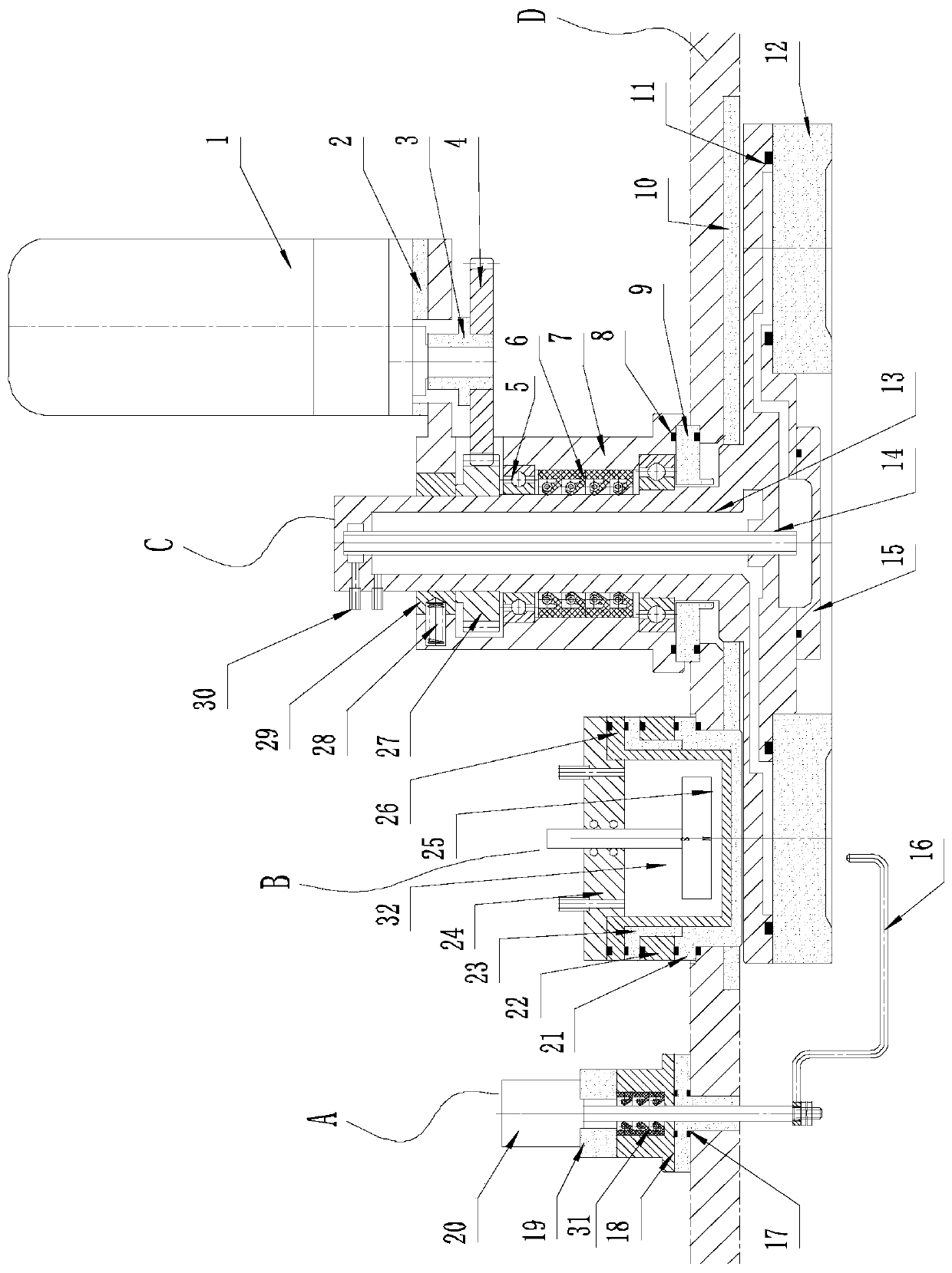
[0033] In this embodiment, a rotary long-life multi-arc target is suitable for continuous coating production, such as figure 1 As shown, it includes arc striking device A, anode device B and rotary arc target device C; the above-mentioned devices that make up the multi-arc target are respectively installed on the installation platform D in the coating chamber. The specific structure of each device is as follows:

[0034] The rotary arc target device includes an annular arc target 12 and a target rotation drive mechanism, the annular arc target is arranged at the output end of the target rotation drive mechanism, and the arc starting device and the anode device are respectively arranged on opposite sides of the annular arc target outside. The target rotation drive mechanism includes a rotation drive motor 1, a rotation drive gear set (comprising a meshed driving gear 4 and a driven gear 27), a rotation shaft seat 13 and a cooling assembly, and the output end of the rotation dri...


PUM


Abstract

The invention discloses a rotary long-service-life multi-arc target and a using method thereof. The rotary long-service-life multi-arc target comprises an arc striking device, an anode device and a rotary electric arc target device, the rotary electric arc target device comprises an annular arc target material and a target material rotation driving mechanism, the annular arc target material is arranged at the output end of the target material rotation driving mechanism, and the arc striking device and the anode device are arranged on the outer sides of the two opposite faces of the annular arctarget material correspondingly. The using method of the rotary long-service-life multi-arc target comprises the following steps: of driving the annular arc target material to continuously rotate through the target material rotation driving mechanism, taking an area between the arc striking device and the anode device as a sputtering area in the rotating process, exciting the surface of the annular arc target material in the sputtering area to sputter a required coating material by using the arc striking device and the anode device which are fixed, and continuously coating a workpiece or a base material passing through the sputtering area. By means of the rotary long-service-life multi-arc target and the using method, the continuous service life of the target material can be effectively prolonged, the target material can be well applied to a continuous coating and long-time working production line, and meanwhile the coating effect is improved.

Description

technical field [0001] The invention relates to the technical field of vacuum coating, in particular to a rotary long-life multi-arc target suitable for continuous coating production and its application method. Background technique [0002] In the field of vacuum coating, the multi-arc target is a commonly used coating source mechanism in the coating room. In a traditional vacuum coating machine, the multi-arc target is generally fixed and installed in the vacuum coating chamber. By setting the arc striking device and the anode device on both sides of the target, the magnetic field in the anode device combined with the arc striking device The arc striking function sputters the coating raw material from the surface of the target to achieve coating on the surface of the workpiece or substrate passing through the range under the multi-arc target. In actual production, since the target is installed in a fixed manner, the position where the target surface is sputtered is in a fi...

Claims


Application Information

Patent Timeline
IPC IPC(8): C23C14/35
CPCC23C14/35C23C14/3407
Inventor 朱建明
Owner ZHAOQING KERUN VACUUM EQUIP
Learn More