Steam turbine high pressure bypass system state monitoring method and system

A system state, steam turbine technology, applied in nuclear methods, mechanical equipment, engine components, etc., can solve problems such as unplanned shutdown of units, prone to over-temperature, equipment damage, etc.

Active Publication Date: 2020-07-14
华润电力技术研究院有限公司
View PDF5 Cites 6 Cited by
  • Summary
  • Abstract
  • Description
  • Claims
  • Application Information

AI Technical Summary

Problems solved by technology

[0004] The high-side system usually uses DCS monitoring. Only when a fault (trip) occurs, the alarm will be detected. It is difficult to find the deterioration trend of the equipment or system deviating from the normal state. When the system fails, it has caused equipment damage or unplanned shutdown of the unit. ;
[0005] The post-valve pressure control of the high-side pressure reducing valve is mostly operated manually. During the start-up period of the unit, the operating personnel operate a lot, and the control is lagging and inaccurate;
[0006] The temperature after the high-side desuperheating water valve controls the high-side pressure-reducing valve is mostly operated manually. During the start-up of the unit, the operating personnel operate a lot, and the control is lagging, inaccurate, prone to over-temperature, and reduces the life of the pipeline;
[0007] There is no monitoring method for the high bypass oil system, and it is difficult to find out the abnormality of the equipment and oil leakage in the oil pipeline through the operation monitoring panel
[0008] Therefore, how to avoid affecting the safety and reliability of the high-side system movement due to the inability to perform real-time status monitoring and automatic control optimization on the high-side system and the equipment is a technical problem that those skilled in the art need to solve at present.

Method used


Image

  • Steam turbine high pressure bypass system state monitoring method and system
  • Steam turbine high pressure bypass system state monitoring method and system
  • Steam turbine high pressure bypass system state monitoring method and system

Examples


Embodiment Construction

[0060] The following will clearly and completely describe the technical solutions in the embodiments of the present invention with reference to the accompanying drawings in the embodiments of the present invention. Obviously, the described embodiments are only some, not all, embodiments of the present invention. Based on the embodiments of the present invention, all other embodiments obtained by persons of ordinary skill in the art without making creative efforts belong to the protection scope of the present invention.

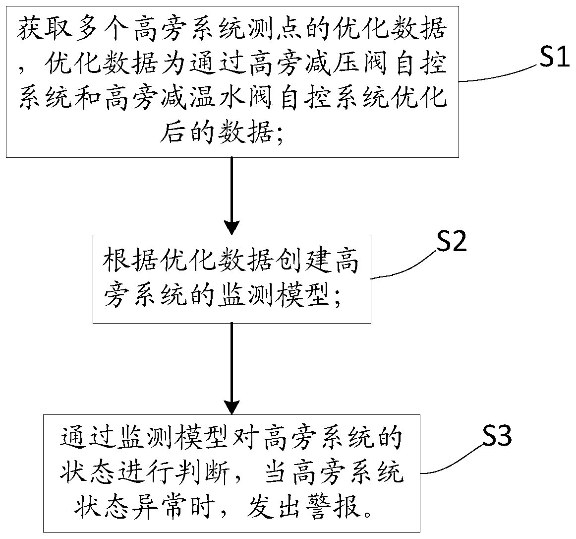
[0061] The core of the present invention is to provide a method for monitoring the state of the high bypass system of a steam turbine. The monitoring method can effectively monitor the high bypass system and its associated equipment in the whole process, and when the state of the high bypass system is abnormal, an alarm can be issued to remind the operating personnel. Check and deal with it in time. Another core of the present invention is to provide a device ...


PUM


Abstract

The invention discloses a steam turbine high pressure bypass system state monitoring method. The method comprises the following steps of obtaining optimized data of a plurality of measuring points ofa high pressure bypass system, wherein the optimized data are data optimized through a high pressure bypass pressure reducing valve automatic control system and a high pressure bypass temperature reducing water valve automatic control system; creating a monitoring model of the high pressure bypass system according to the optimized data; and judging the state of the high pressure bypass system through the monitoring model, and giving an alarm when the state of the high pressure bypass system is abnormal. The invention further discloses a system applied to the steam turbine high pressure bypasssystem state monitoring method. The steam turbine high pressure bypass system state monitoring method can give an alarm when the high pressure bypass pressure reducing valve and the high pressure bypass temperature reducing water valve of the high pressure bypass system are abnormal and the steam pressure and the temperature behind the high pressure bypass pressure reducing valve are abnormal so as to remind an operator to check and process in time, and therefore the state of the high pressure bypass system can be effectively monitored.

Description

technical field [0001] The invention relates to the technical field of thermal power generation, in particular to a state monitoring method for a high bypass system of a steam turbine. The invention also relates to a steam turbine high bypass system state monitoring system applied to the steam turbine high bypass system state monitoring method. Background technique [0002] With the increasingly market-oriented development of the power system, thermal power plants are undertaking more and more peak-shaving functions, and the units are required to have the ability to start and stop at any time on the basis of stable operation. Therefore, the number of starts and stops of the units continues to increase. Automatically adjust and operate at 30% to 100% rated load, which puts forward higher requirements for the automation control level of thermal power plant equipment. As the most important operation and adjustment system in the start-up process of the unit, the system is more ...

Claims


Application Information

Patent Timeline
IPC IPC(8): F01D21/00F01D21/12G06N20/10
CPCF01D21/003F01D21/00F01D21/12G06N20/10
Inventor 卫平宝聂怀志陈建华张含智马成龙袁雪峰李晓静陈世和姜利辉
Owner 华润电力技术研究院有限公司
Why Eureka
Try Eureka