Sound production device

A sound-emitting device and skeleton technology, applied in the field of electro-acoustic conversion, can solve the problems of limiting the loudness of the sound-emitting device, limiting the BL value, and small effective vibration area of ​​the diaphragm, achieving large driving force, increasing the BL value of the magnetic field, and improving the effectiveness of the diaphragm. The effect of vibrating area

Active Publication Date: 2020-07-10
AAC TECH PTE LTD
View PDF4 Cites 6 Cited by
  • Summary
  • Abstract
  • Description
  • Claims
  • Application Information

AI Technical Summary

Problems solved by technology

[0003] However, in the sound-generating device of the related art, the vibration system and the magnetic circuit system are stacked up and down, and the structure of the magnetic circuit system is limited in the sound-generating device of the same height, thereby limiting the BL value of its magnetic field; in addition , the sound-generating device has only one diaphragm structure, and the effective vibration area (SD) of the diaphragm is small, thereby limiting the loudness of the sound-generating device

Method used


Image

  • Sound production device
  • Sound production device
  • Sound production device

Examples


Embodiment Construction

[0044] The following will clearly and completely describe the technical solutions in the embodiments of the present invention with reference to the accompanying drawings in the embodiments of the present invention. Obviously, the described embodiments are only some, not all, embodiments of the present invention. Based on the embodiments of the present invention, all other embodiments obtained by persons of ordinary skill in the art without making creative efforts belong to the protection scope of the present invention.

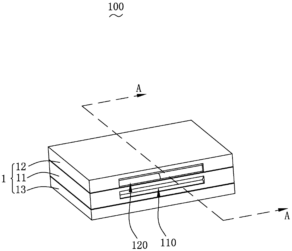
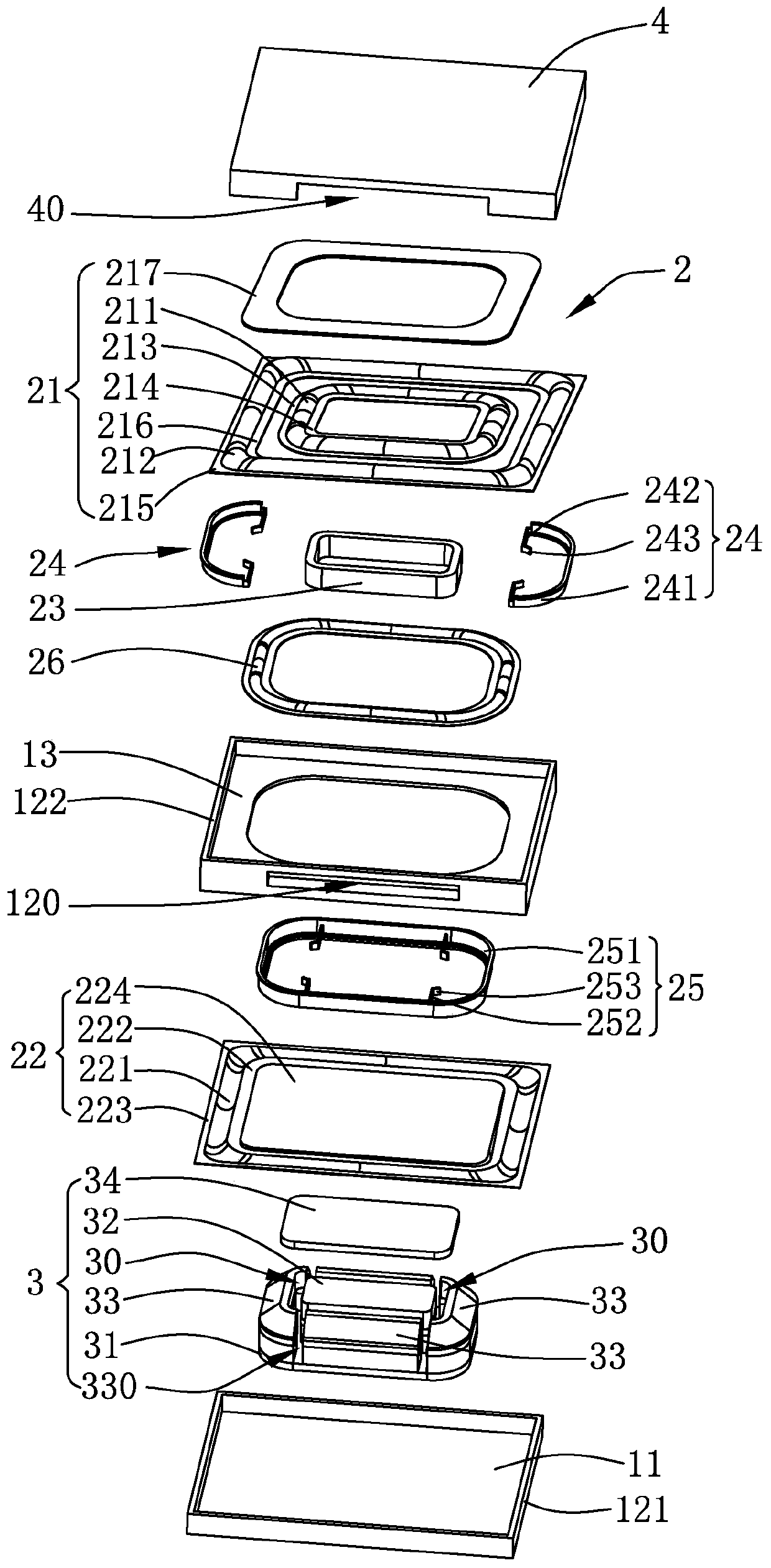
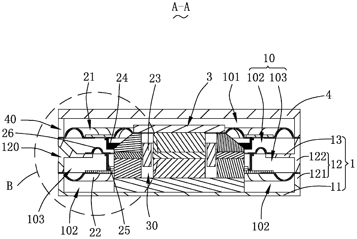
[0045] Please also see Figure 1-10 , the present invention provides a sound-generating device 100, which includes a basin frame 1, a vibration system 2, a magnetic circuit system 3 and an upper cover plate 4 respectively supported on the basin frame 1, and the magnetic circuit system 3 has a magnetic gap 30 , the magnetic circuit system 3 drives the vibration system 2 to vibrate and produce sound.

[0046] The vibration system 2 includes an upper diaphragm 2...


PUM


Abstract

The invention provides a sound production device. The sound production device comprises a basin stand, a vibration system and a magnetic circuit system. The vibration system comprises an annular uppervibrating diaphragm, an annular lower vibrating diaphragm, an annular voice coil, an annular upper framework, an annular lower framework and an annular isolation vibrating diaphragm. The upper vibrating diaphragm is fixed to the basin frame and defines a containing space together with the basin frame, the side, away from the containing space, of the upper vibrating diaphragm communicates with theoutside and serves as an upper front cavity for the upper vibrating diaphragm to produce sound, and the upper vibrating diaphragm is arranged around the magnetic circuit system at intervals. The lower vibrating diaphragms are arranged around the magnetic circuit system at intervals, and the peripheral sides of the lower vibrating diaphragms are fixed on the basin stand. The upper framework is respectively connected with the upper vibrating diaphragm and the voice coil. The lower framework is respectively connected with the lower vibrating diaphragm and the voice coil. The outer peripheral side of the isolation diaphragm is connected with the basin stand body, the inner peripheral side of the isolation diaphragm is connected with the lower skeleton, and the lower diaphragm, the lower skeleton, the isolation diaphragm and the basin stand jointly divide the accommodation space into a lower front cavity used for sounding of the lower diaphragm and a rear cavity used for sharing of the upper diaphragm and the lower diaphragm. Compared with the prior art, the sound production device is higher in acoustic loudness and better in acoustic performance.

Description

【Technical field】 [0001] The invention relates to the field of electroacoustic conversion, in particular to a sound generating device used in electronic sound box products. 【Background technique】 [0002] The sound-generating device in the related art includes a pot frame, a vibration system fixed to the pot frame, and a magnetic circuit system with a magnetic gap. The magnetic circuit system drives the vibration system to vibrate and produce sound. The vibration system includes a The frame is used to vibrate and sound the diaphragm, the dome attached to the diaphragm is close to the skeleton on the side of the magnetic circuit system, and the sound is inserted in the magnetic gap and connected with the skeleton to drive the diaphragm to vibrate. lock up. [0003] However, in the sound-generating device of the related art, the vibration system and the magnetic circuit system are stacked up and down, and the structure of the magnetic circuit system is limited in the sound-ge...

Claims


Application Information

Patent Timeline
Patent Type & Authority Applications(China)
IPC IPC(8): H04R9/02H04R9/06H04R7/12
CPCH04R7/125H04R9/02H04R9/025H04R9/06
Inventor 宋威张帆金鑫
Owner AAC TECH PTE LTD
Why Eureka
Try Eureka