Optical fiber damage monitoring system by analyzing various environmental vibration signals

A vibration signal and monitoring system technology, applied in transmission monitoring/testing/fault measurement systems, optical instrument testing, testing optical fiber/optical waveguide equipment, etc., can solve problems such as fiber breakage and damage

Active Publication Date: 2020-07-10
SHENZHEN SDG INFORMATION CO LTD
View PDF8 Cites 1 Cited by
  • Summary
  • Abstract
  • Description
  • Claims
  • Application Information

AI Technical Summary

Problems solved by technology

[0005] Aiming at the deficiencies of the prior art, the present invention provides an optical fiber damage monitoring system by analyzing various environmental vibration signals, which solves the problem that personnel fail to discover in time that the internal fiber is damaged due to the leakage of the outer skin of the optical fiber, which eventually leads to the physical damage caused by the fiber breaking. damage problem

Method used


Image

  • Optical fiber damage monitoring system by analyzing various environmental vibration signals
  • Optical fiber damage monitoring system by analyzing various environmental vibration signals

Examples


Embodiment Construction

[0028] The following will clearly and completely describe the technical solutions in the embodiments of the present invention with reference to the accompanying drawings in the embodiments of the present invention. Obviously, the described embodiments are only some, not all, embodiments of the present invention. Based on the embodiments of the present invention, all other embodiments obtained by persons of ordinary skill in the art without making creative efforts belong to the protection scope of the present invention.

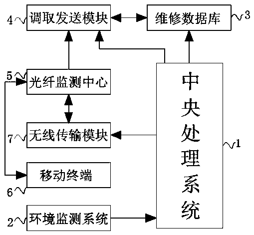
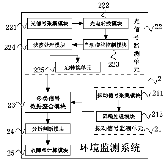
[0029] see Figure 1-2, the embodiment of the present invention provides a technical solution: an optical fiber damage monitoring system by analyzing various environmental vibration signals, which can realize the collection, analysis and judgment of vibration signals and optical signals in various regional environments under the coverage of the optical fiber network Finally, calculate the specific location of the fault point, and notify the maintenance personn...


PUM


Abstract

The invention discloses an optical fiber damage monitoring system by analyzing various environmental vibration signals. A central processing system is included. An input end of the central processingsystem is electrically connected with an output end of an environment monitoring system through a wire. The environment monitoring system comprises a vibration signal monitoring unit and an optical signal monitoring unit, the optical signal monitoring unit comprises an optical signal acquisition module, and the output end of the optical signal acquisition module is electrically connected with theinput end of a photoelectric conversion module through the wire. The invention relates to the field of an optical fiber communication technology. By using the optical fiber damage monitoring system byanalyzing the various environmental vibration signals, vibration signals and optical signals in various area environments covered by an optical fiber network can be collected, analyzed and judged, then a specific position of a fault point is calculated, maintenance personnel are informed to carry out rush repair at the first time, and a problem that the network is thoroughly interrupted due to afact that fibers in an optical fiber are finally broken is solved.

Description

technical field [0001] The invention relates to the technical field of optical fiber communication, in particular to an optical fiber damage monitoring system by analyzing various environmental vibration signals. Background technique [0002] Optical fiber communication technology stands out from optical communication and has become one of the main pillars of modern communication. It plays a pivotal role in modern telecommunication networks. As an emerging technology, optical fiber communication has developed rapidly in recent years and has a wide range of applications. It is rare in the history of communication, and it is also an important symbol of the world's new technological revolution and the main transmission tool for various information in the future information society. Optical fiber is the abbreviation of optical fiber. A communication method. From a principle point of view, the basic material elements that constitute optical fiber communication are optical fibers,...

Claims


Application Information

Patent Timeline
Patent Type & Authority Applications(China)
IPC IPC(8): G01M11/00G01H9/00H04B10/07
CPCG01H9/004G01M11/30H04B10/07
Inventor 邓伟锋徐常志叶俊健陈晓波
Owner SHENZHEN SDG INFORMATION CO LTD
Why Eureka
Try Eureka