
Nylon ring nesting device for nylon self-locking nut

A self-locking nut and nylon technology, which is applied to threaded products, other household appliances, household appliances, etc., can solve the problems of reduced efficiency, high positioning requirements, and high degree of cooperation between the outer diameter of the nylon ring and the stepped hole.

Active Publication Date: 2020-07-10
海盐沛泓汽车零部件有限公司
View PDF22 Cites 3 Cited by
  • Summary
  • Abstract
  • Description
  • Claims
  • Application Information

AI Technical Summary

Problems solved by technology

[0004] The disadvantages of the above-mentioned device are as follows: 1. The outer diameter of the nylon ring is highly compatible with the step hole, and the nylon ring itself is made of soft material, so the positioning requirement for the step of inserting the nylon ring into the step hole is high. The device, the blanking hole and the pressing device realize this step, and the positioning accuracy can be further improved; 2. The detection device detects that there is no nylon ring, and the whole device stops, and then the nylon ring is manually inserted, which reduces the efficiency. , also increases the workload of workers

Method used


Image

  • Nylon ring nesting device for nylon self-locking nut
  • Nylon ring nesting device for nylon self-locking nut
  • Nylon ring nesting device for nylon self-locking nut

Examples


Embodiment Construction

[0035] The following descriptions are only preferred implementations of the present invention, and the scope of protection is not limited to this embodiment. All technical solutions under the idea of ​​the present invention shall belong to the scope of protection of the present invention. At the same time, it should be pointed out that for those of ordinary skill in the art, some improvements and modifications without departing from the principle of the present invention should also be regarded as the protection scope of the present invention. Left, right, etc. are defined based on the top view. It should be understood that the use of the orientation words should not limit the scope of protection claimed by this application.

[0036] The center of the wooden workbench is provided with a through hole, the bottom of the wooden workbench is fixedly connected with the second stepping motor, the rotating shaft of the second stepping motor passes through the through hole, and the rot...


PUM


Abstract

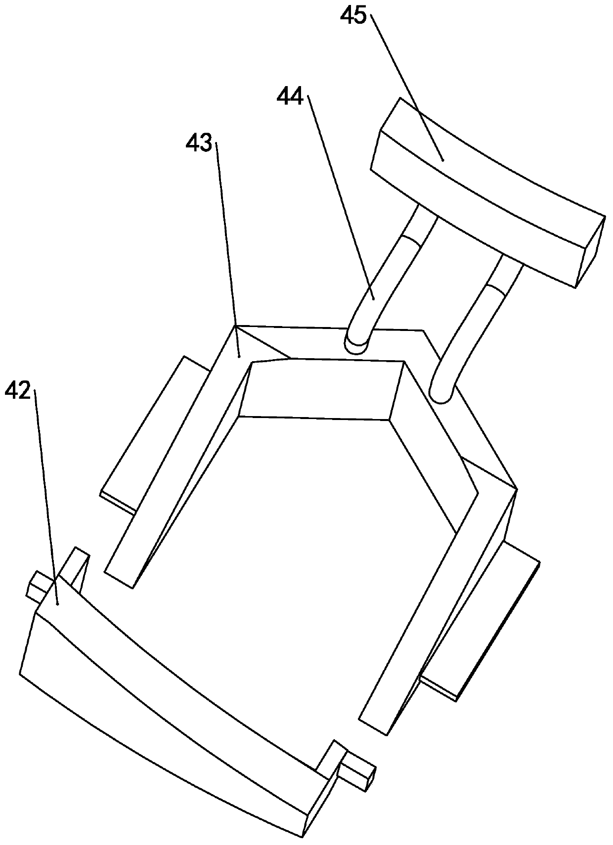
The invention discloses a nylon ring nesting device for a nylon self-locking nut. The nylon ring nesting device comprises a feeding mechanism, a detection mechanism and a loading and unloading mechanism; the feeding mechanism comprises a lifting unit and a downward pressing unit; the downward pressing unit comprises an L-shaped plate, two pressing plates, two air cylinders I and two air cylindersII; the center of a horizontal plate of the L-shaped plate is provided with a rectangular through slot, and the horizontal plate is located above a round turntable; each pressing plate comprises a semi-circular sleeve and an L-shaped side plate; horizontal parts and vertical parts of the L-shaped side plates are slidably connected with telescopic rods of the air cylinders I and the air cylinders II respectively; the air cylinders I and the air cylinders II are fixedly connected with an L-shaped rack; the detection mechanism comprises a metal sheet I and a metal sheet II; the metal sheet I is arranged on the surface of a wooden workbench and right below the L-shaped plate; the metal sheet II is arranged at the bottom surface of the semi-circular sleeve of one of the pressing plates; when there is a nylon ring, the nylon ring is insulated, and the two metal sheets are not conductive; and when there is no nylon ring, the two metal sheets are in contact with a nut body, and can be conductive.

Description

technical field [0001] The invention relates to the field of production and processing of nylon self-locking nuts, in particular to a nylon ring nesting device for nylon self-locking nuts. Background technique [0002] Nut is a common fastener, generally used in conjunction with bolts, many bolts and nuts are used in vibration situations, vibration will also cause the connection between bolts and nuts to loosen, resulting in potential safety hazards, so self-locking nuts are used Nylon self-locking nuts are a kind of self-locking nuts. Compared with ordinary nuts, nylon self-locking nuts add a layer of nylon ring. The nylon ring is ring-shaped. The inner diameter of the nylon ring is slightly larger than the threaded hole diameter of the nut. In such use, the external thread of the bolt and the nylon ring are extruded to deform the nylon ring. After installation, the nylon ring and the thread are completely squeezed into contact, and the extruded nylon ring produces a large ...

Claims


Application Information

Patent Timeline
Patent Type & Authority Applications(China)
IPC IPC(8): B29C65/56B29C65/64B29C65/78B29L1/00
CPCB29C65/56B29C65/64B29C65/78B29C65/7858B29C66/8242B29L2001/005
Inventor 林奕志
Owner 海盐沛泓汽车零部件有限公司
Learn More