
Novel universal variable rigidity manipulator joint

A variable stiffness, robotic arm technology, applied in the directions of manipulators, manufacturing tools, joints, etc., can solve the problems of robot structure damage, destruction of operating objects, endangering operators, etc., to achieve huge application potential, increase reliability, and facilitate integration.

Active Publication Date: 2020-07-10
BEIJING INST OF CONTROL ENG
View PDF8 Cites 4 Cited by
  • Summary
  • Abstract
  • Description
  • Claims
  • Application Information

AI Technical Summary

Problems solved by technology

[0002] For a multi-joint robot for operation, if it is facing an unstructured environment, collision or contact between the operating end and the environment is inevitable. Rigid collisions may cause permanent damage to the robot structure, and can destroy the operating object or endanger the operator
There are mainly two solutions to this destructive collision. One is to adjust the contact force and moment between the contact object and the contact object through the software design of the compliant control algorithm to ensure the safety of the contact. However, this method is subject to the entire control system. Bandwidth constraints, unable to respond quickly

Method used


Image

  • Novel universal variable rigidity manipulator joint
  • Novel universal variable rigidity manipulator joint
  • Novel universal variable rigidity manipulator joint

Examples


Embodiment

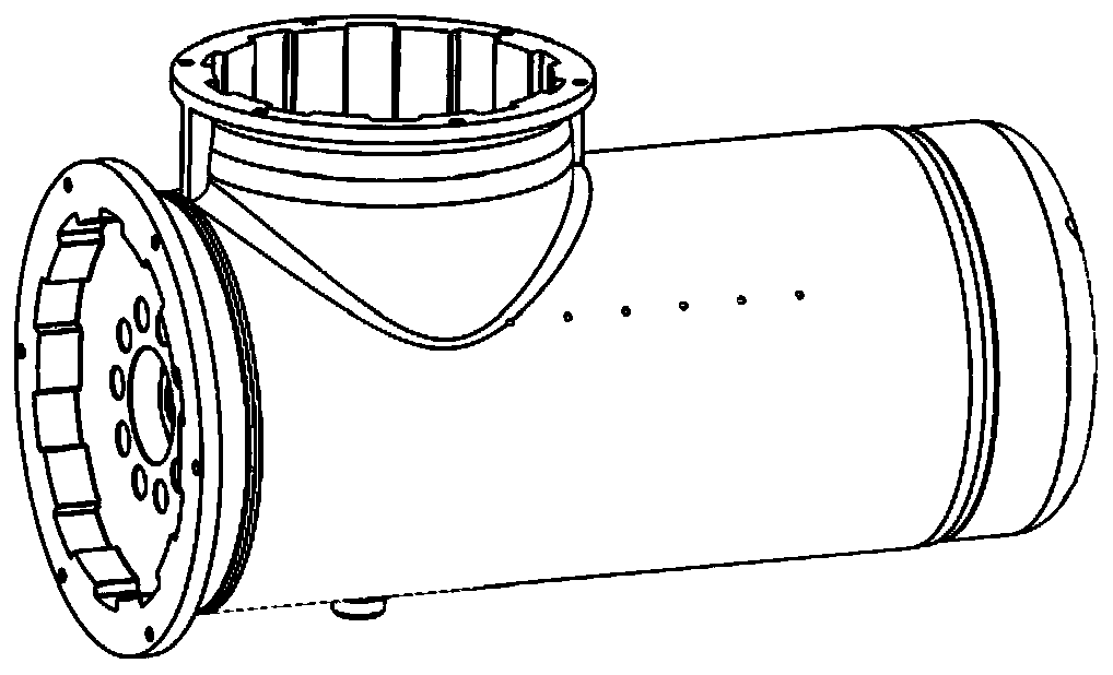
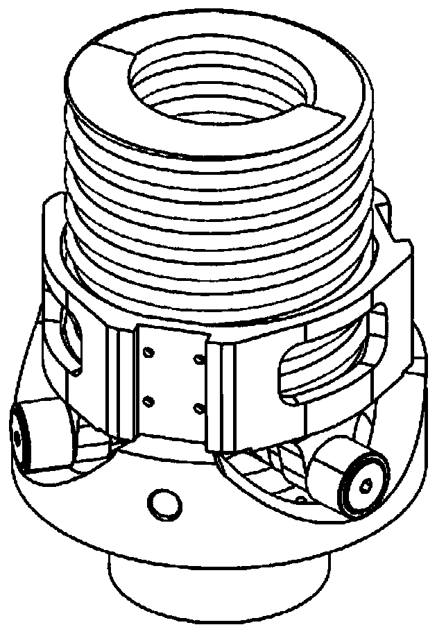
[0044] Figure 6 The arc-shaped wheel disc provides a preferred structural form capable of realizing the above-mentioned functions.

[0045] Such as Figure 6 As shown, one side of the arc-shaped wheel is the hollow shaft shown in the figure, and the inner side of the shaft is an internal spline. The arc-shaped wheel is connected to the output flange through the spline and the end locking screw. hole through. The other side of the arc-shaped wheel has a three-part concave arc surface symmetrically distributed on the circumference. The arc surface adopts a Bezier curve design to provide a rolling contact surface for the roller bearing. The highest points on both sides of the concave arc surface, the arc surface Perpendicular to the face of the roulette. On the same side, a concave-convex engaging surface is provided around the middle through hole, which can cooperate with the concave-convex engaging surface of the screw nut fixing plate to limit the rotation of the arc-shape...


PUM


Abstract

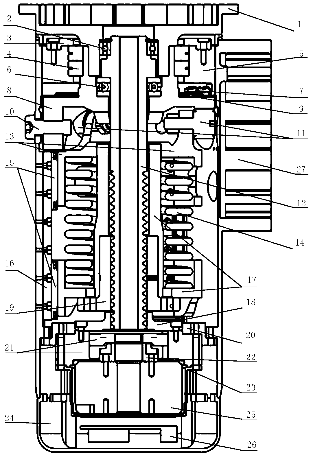
The invention discloses a novel universal variable rigidity manipulator joint. The output of a harmonic reducer is fixedly connected with a threaded end of a trapezoidal lead screw; when the trapezoidal lead screw rotates, a lead screw nut and the trapezoidal lead screw can produce relative axial movement; the lead screw nut is fixedly connected with a lead screw nut fixing disc; the lead screw nut fixing disc and a roller bearing disc can perform axial movement relative to a joint shell along a guide rail fixed to the inner side of the joint shell; a mould spring is mounted between the lead screw nut fixing disc and the roller bearing disc in a sleeving manner; an arc-shaped wheel disc is mounted between the roller bearing disc and a horizontal end of the trapezoidal lead screw; the arc-shaped wheel disc is mounted on the trapezoidal lead screw in the sleeving manner; the horizontal end of the trapezoidal lead screw positions the trapezoidal lead screw in the radial direction througha bearing, bears the acting force of the mould spring and transfers the acting force of the mould spring to the arc-shaped wheel disc; the arc-shaped wheel disc is fixedly connected to an output flange, and is supported to rotate relative to the joint shell through the bearing; and the arc-shaped wheel disc is matched with a roller bearing mounted on the roller bearing disc, so that the external acting force acting on an output flange is converted into compression force acting on the spring.

Description

technical field [0001] The invention belongs to the field of mechanical arm joint design and relates to a novel universal variable stiffness mechanical arm joint. Background technique [0002] For a multi-joint robot for operation, if it is facing an unstructured environment, collision or contact between the operating end and the environment is inevitable. Rigid collisions may cause permanent damage to the robot structure, and can destroy the operating object or endanger the operator. There are mainly two solutions to this destructive collision. One is to adjust the contact force and moment between the contact object and the contact object through the software design of the compliant control algorithm to ensure the safety of the contact. However, this method is subject to the entire control system. Bandwidth constraints make it impossible to respond quickly. Another method is to improve the hardware design, using joints with active stiffness adjustment, and adding a flexib...

Claims


Application Information

Patent Timeline
IPC IPC(8): B25J17/02
CPCB25J17/02
Inventor 胡勇魏春岭刘磊王勇徐拴锋
Owner BEIJING INST OF CONTROL ENG
Learn More