
Speed measurement positioning method and terminal

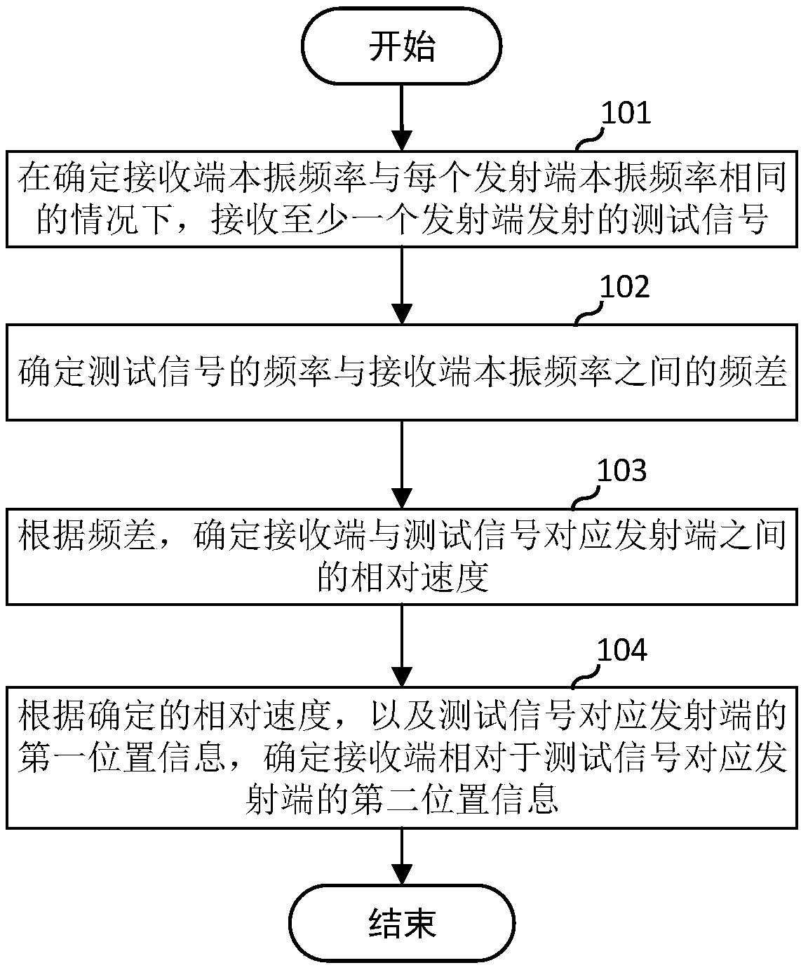
A speed measurement and terminal technology, which is used in positioning, location-based services, measurement devices, etc., and can solve problems such as large reflection area and limited use of speed measurement and positioning systems.

Inactive Publication Date: 2020-07-07
ZTE CORP
View PDF9 Cites 3 Cited by
  • Summary
  • Abstract
  • Description
  • Claims
  • Application Information

AI Technical Summary

Problems solved by technology

[0004] The inventor finds that there are at least the following problems in the prior art: current traffic speed measuring radars usually sample millimeter waves for speed measurement, but using radar for speed measurement requires that the target can reflect back the signal, so the target should be metal; and in order to ensure The radar can receive the reflection signal reflected by the target, and the target needs to meet the large reflection area. The above problems greatly limit the use of the speed measurement and positioning system

Method used


Image

  • Speed measurement positioning method and terminal
  • Speed measurement positioning method and terminal
  • Speed measurement positioning method and terminal

Examples


Embodiment Construction

[0021] In order to make the purpose, technical solutions and advantages of the embodiments of the present invention more clear, various implementation modes of the present invention will be described in detail below in conjunction with the accompanying drawings. However, those of ordinary skill in the art can understand that, in each implementation manner of the present invention, many technical details are provided for readers to better understand the present application. However, even without these technical details and various changes and modifications based on the following implementation modes, the technical solution claimed in this application can also be realized.

[0022] The first embodiment of the present invention relates to a method for speed measurement and positioning. The speed measurement and positioning method is applied to a receiving end, and the receiving end may be a terminal, for example, a smart phone, an electronic vehicle-mounted device, a positioning ...


PUM


Abstract

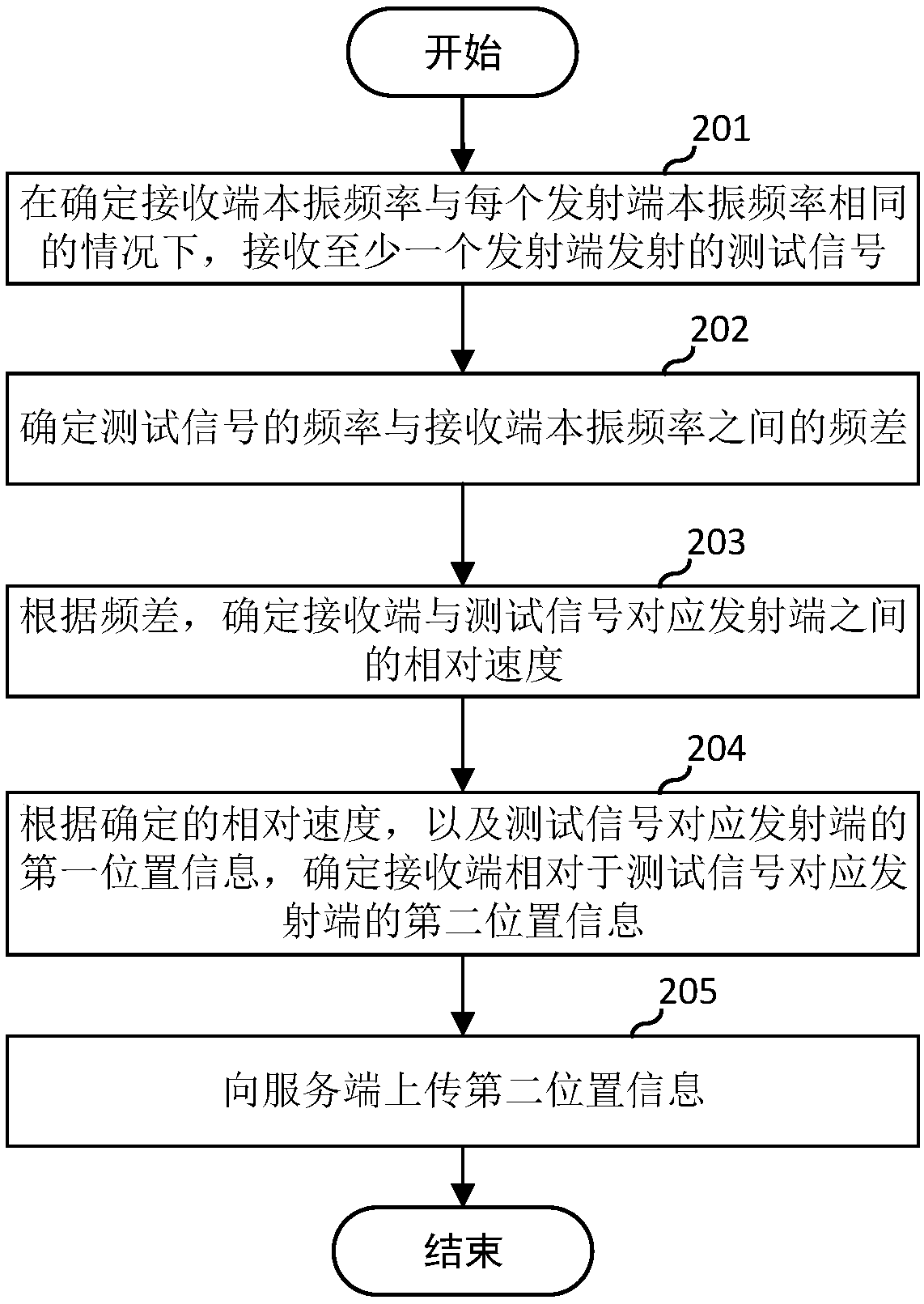
The embodiment of the invention relates to the field of wireless communication, and discloses a speed measurement positioning method and a terminal. The speed measurement positioning method is appliedto a receiving end, and comprises: receiving a test signal transmitted by at least one transmitting end under the condition of determining that the local oscillation frequency of the receiving end isthe same as the local oscillation frequency of each transmitting end, determining a frequency difference between the frequency of the test signal and the local oscillation frequency of the receivingend, determining a relative speed between the receiving end and the transmitting end corresponding to the test signal according to the frequency difference, and determining second position informationof the receiving end relative to the transmitting end corresponding to the test signal according to the determined relative speed and the first position information of the transmitting end corresponding to the test signal. According to the embodiment, a target at any distance can be subjected to distance measurement and positioning, and the speed measurement and positioning application range is widened.

Description

technical field [0001] The embodiments of the present invention relate to the field of wireless communication, and in particular, to a method and terminal for speed measurement and positioning. Background technique [0002] The Doppler effect is that when vibration sources such as sound, light, and radio waves move relative to the observer at a relative speed, the vibration frequency received by the observer is different from the frequency emitted by the vibration source. Because this phenomenon was first discovered by the Austrian scientist Doppler, it is called the Doppler effect. The frequency change caused by the Doppler effect is called Doppler shift, which is directly proportional to the relative velocity and inversely proportional to the vibration frequency. [0003] The Doppler speed measurement and positioning system is a system that uses the Doppler effect of microwaves for speed measurement, ranging and positioning. For example, traffic speed radar. The working...

Claims


Application Information

Patent Timeline
Patent Type & Authority Applications(China)
IPC IPC(8): H04W4/02H04W64/00G01S13/06G01S13/58H04J3/06H04W4/021
CPCH04W4/02H04W4/027G01S13/06G01S13/58H04W64/00G01S5/0284G01S11/08G01S5/0246G01S11/10G01S2205/01G01S1/60G01S13/583H04W56/001H04W56/0035
Inventor 罗迤宝
Owner ZTE CORP
Learn More