Eureka AIR delivers breakthrough ideas for toughest innovation challenges, trusted by R&D personnel around the world.

Multi-energy illuminating lamp

A lighting and multi-energy technology, which is applied in the direction of lighting devices, lighting auxiliary devices, lighting and heating equipment, etc., can solve the problems of being unable to support, affecting lighting effects, reducing the service life of lamps, etc.

Inactive Publication Date: 2020-07-07
漳浦县中诺生物科技有限公司
View PDF6 Cites 0 Cited by
  • Summary
  • Abstract
  • Description
  • Claims
  • Application Information

AI Technical Summary

Problems solved by technology

[0004] The purpose of the present invention is to provide a multi-energy lighting lamp to solve the problem that the existing multi-energy lighting lamp proposed in the above background technology is not easy to place when in use because the lamp body is a cylinder, and it often falls apart due to rolling. Falling on the ground brought damage to it, reduced the service life of the lamp, and at the same time it could not be supported during work, which greatly reduced the work efficiency of the staff, and the existing multi-energy lighting lamp , when placed for a long time, it will cause a certain amount of dust to accumulate on the lampshade, which will affect the lighting effect

Method used


Image

  • Multi-energy illuminating lamp
  • Multi-energy illuminating lamp
  • Multi-energy illuminating lamp

Examples


Embodiment Construction

[0021] The following will clearly and completely describe the technical solutions in the embodiments of the present invention with reference to the accompanying drawings in the embodiments of the present invention. Obviously, the described embodiments are only some of the embodiments of the present invention, not all of them. Based on the embodiments of the present invention, all other embodiments obtained by persons of ordinary skill in the art without making creative efforts belong to the protection scope of the present invention.

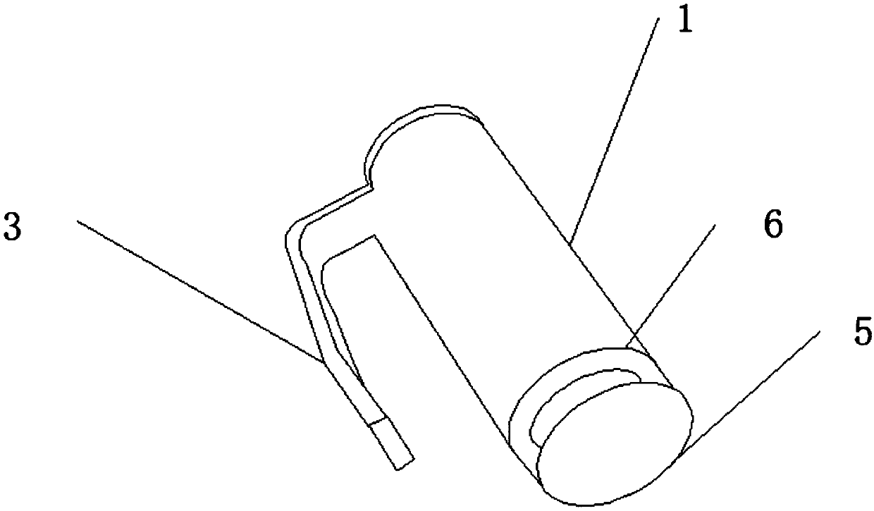
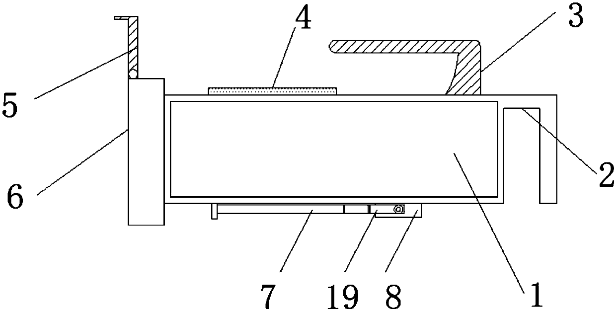
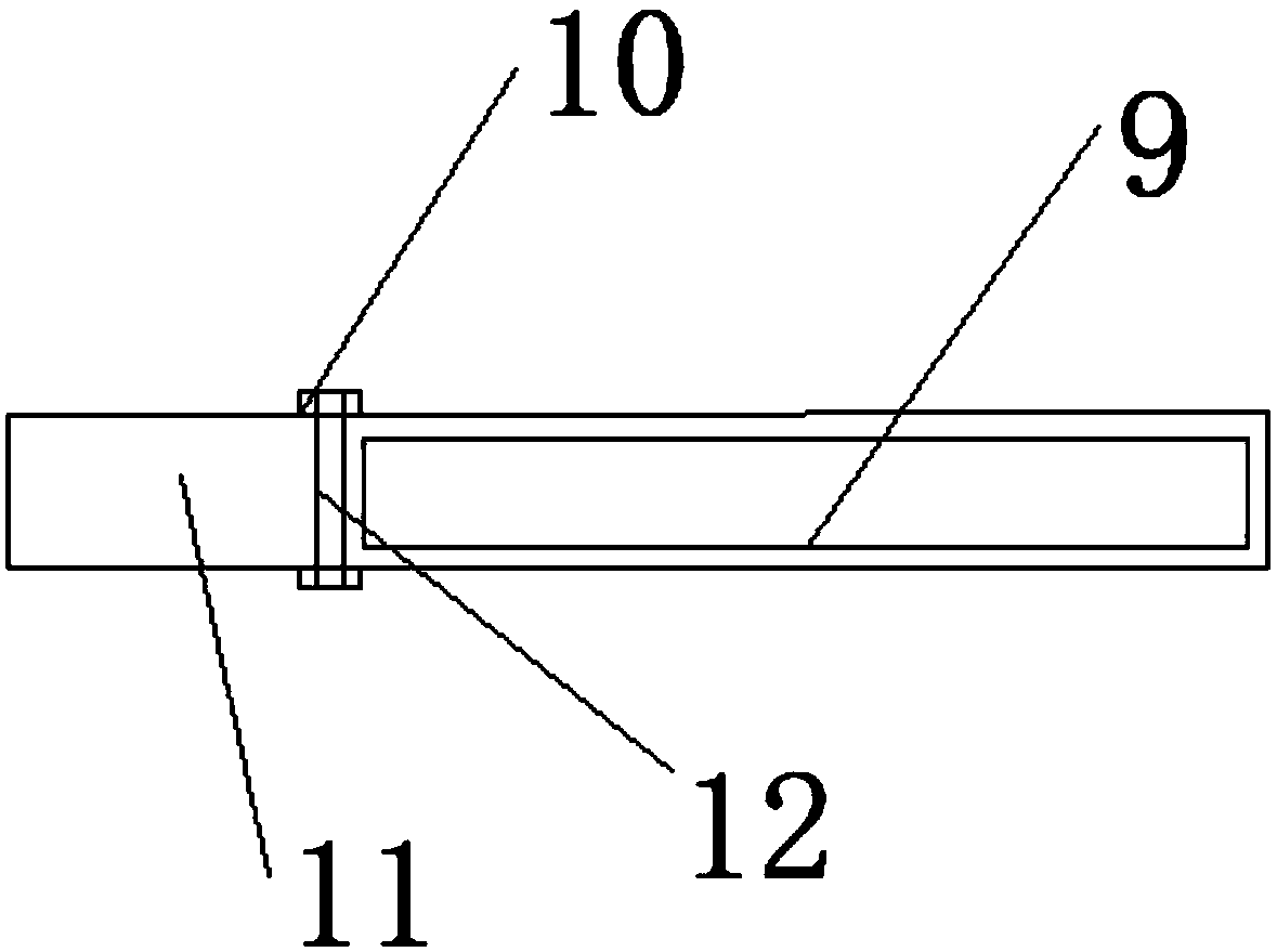
[0022] see Figure 1-Figure 5 , the present invention provides a technical solution: a multi-energy lighting lamp, including a lamp body 1, a lampshade 6 is fixedly connected to the outer side of the lamp body 1, and a dust-shielding mechanism is fixedly connected to the outer side of the lampshade 6, and the dust-shielding mechanism Including the connecting shaft B13 at the top of the lampshade 6, the two ends of the connecting shaft B13 are fix...


PUM


Abstract

The invention discloses a multi-energy illuminating lamp. The lamp comprises a lamp body, a lampshade is fixedly connected to one side of the outer portion of the lamp body. One side of the outer partof the lampshade is fixedly connected with a dust shielding mechanism; the dust shielding mechanism comprises a connecting shaft B at the top end of the lampshade; fixing bolts B are fixedly connected to the two ends of the connecting shaft B; a dust shielding cover is fixedly connected to the surface of the top end of the connecting shaft B; a limiting rod is fixedly connected to one end of theouter surface of the dust shielding cover, a connecting shaft A is fixedly connected to one end of the limiting rod, fixing bolts A are fixedly connected to the two ends of the connecting shaft A, a fixed rod is fixedly connected to one side of the outer portion of the connecting shaft A, and the middle of the lower surface of the lamp body is fixedly connected with a supporting mechanism. By designing the dust shielding mechanism installed on the surface of the top end of the lampshade, the outer surface of the lampshade can be effectively prevented from dust, and the situation that when thelamp is not used for a long time, certain dust is accumulated outside the lampshade, and consequently the lighting effect is affected is avoided.

Description

technical field [0001] The invention belongs to the technical field of multi-energy lighting lamps, and in particular relates to a multi-energy lighting lamp. Background technique [0002] The role of lighting fixtures is not limited to lighting, but also the eyes of the home, more often it plays a decorative role. Therefore, the choice of lighting fixtures is much more complicated. It not only involves safety and energy saving, but also involves many factors such as material, type, style and taste. A good lighting may become the soul of the decoration at once. [0003] An existing multi-energy lighting lamp is not easy to place because the lamp body is a cylinder when it is in use, and it often falls on the ground due to rolling, causing damage to it and reducing the service life of the lamp. At the same time, it cannot be supported during work, which greatly reduces the working efficiency of the staff. Moreover, when the existing multi-energy lighting lamp is placed for ...

Claims


Application Information

Patent Timeline
Patent Type & Authority Applications(China)
IPC IPC(8): F21L4/08F21V21/08F21V31/00
CPCF21L4/08F21V21/08F21V31/00
Inventor 涂红云
Owner 漳浦县中诺生物科技有限公司
Why Eureka
Eureka Blog
Learn More