
Charging pile with balancing function and control method

A control method and charging pile technology, applied in battery/fuel cell control devices, charging stations, electric vehicle charging technology, etc., can solve problems such as weak balancing ability, large heat generation, and battery life decay

Pending Publication Date: 2020-07-07
守恒新能源(重庆)有限公司
View PDF9 Cites 0 Cited by
  • Summary
  • Abstract
  • Description
  • Claims
  • Application Information

AI Technical Summary

Problems solved by technology

[0002] The charging piles currently on the market do not have the equalization function when charging, and can only rely on the equalization function of the BMS of the new energy vehicle battery ("new energy vehicle battery" hereinafter referred to as "battery") for equalization, because the BMS equalization current is very small ( The single-cell equalization current is only about 20mA~200mA), the equalization ability is very weak, and the balance requirement of the battery cannot be met, so the battery cannot be repaired within a slow charging cycle, resulting in accelerated decay of battery life
In view of the above factors, when the user needs to balance the battery, it is necessary to go to the designated place and have professionals use professional equipment to balance the battery. Special equipment is expensive
[0003] Moreover, the charging module in the existing charging pile generates a lot of heat during charging, and the charging pile needs to meet the protection requirements, and the charging module must be in a confined space, which leads to a contradiction between the heat dissipation of the charging module and the requirements of the confined space, which in turn affects the use Life expectancy, and there are certain safety hazards

Method used


Image

  • Charging pile with balancing function and control method

Examples


Embodiment Construction

[0038] Embodiments of the present invention are described in detail below, examples of which are shown in the drawings, wherein the same or similar reference numerals designate the same or similar elements or elements having the same or similar functions throughout. The embodiments described below by referring to the figures are exemplary only for explaining the present invention and should not be construed as limiting the present invention.

[0039]In describing the present invention, it should be understood that the terms "longitudinal", "transverse", "upper", "lower", "front", "rear", "left", "right", "vertical", The orientation or positional relationship indicated by "horizontal", "top", "bottom", "inner", "outer", etc. are based on the orientation or positional relationship shown in the drawings, and are only for the convenience of describing the present invention and simplifying the description, rather than Nothing indicating or implying that a referenced device or eleme...


PUM


Abstract

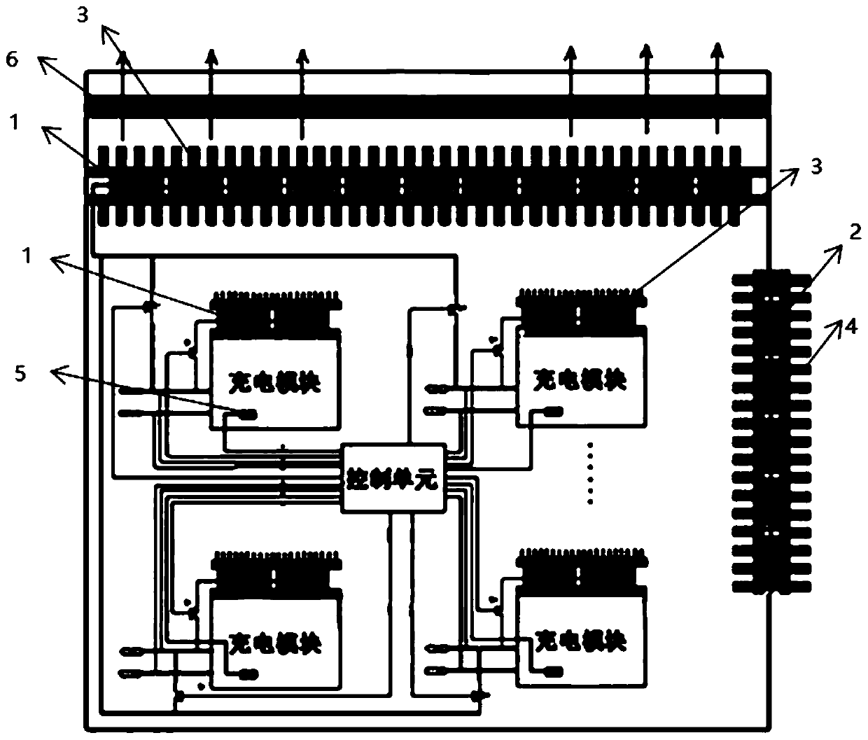
The invention belongs to the technical field of charging pile equipment, and particularly discloses a charging pile with a balancing function and a control method. The charging pile comprises a temperature control equalization system, a control unit, at least one charging module, a charging detection module and a temperature sensor for detecting the temperature of the internal the charging pile are arranged in the charging pile, the output end of the temperature sensor is connected with the temperature information input end of the control unit, the charging pile further comprises a voltage sensor that detects the voltage of the battery to be charged, and the output end of the voltage sensor is connected with the voltage information input end of the control unit; and the temperature controlequalization system comprises a first refrigeration sheet part arranged on the charging module and / or the charging pile shell and a second refrigeration sheet part arranged on the charging pile shell, the first refrigeration sheet part and the second refrigeration sheet part are both controlled by the control unit, and the second refrigeration sheet part is connected with the battery to be charged. By adopting the technical scheme, rapid equalization of the new to-be-charged battery is realized through the temperature control equalization system, and meanwhile, the temperature of the chargingpile is regulated and controlled.

Description

technical field [0001] The invention belongs to the technical field of charging pile equipment, and relates to a charging pile with an equalizing function and a control method. Background technique [0002] The charging piles currently on the market do not have the equalization function when charging, and can only rely on the equalization function of the BMS of the new energy vehicle battery ("new energy vehicle battery" hereinafter referred to as "battery") for equalization, because the BMS equalization current is very small ( The single-cell equalization current is only about 20mA~200mA), and the equalization ability is very weak, which cannot meet the battery equalization requirements, resulting in the battery not being able to complete the repair within a slow charging cycle, resulting in accelerated battery life decay. In view of the above factors, when the user needs to balance the battery, it is necessary to go to the designated place and have professionals use profes...

Claims


Application Information

Patent Timeline
Patent Type & Authority Applications(China)
IPC IPC(8): B60L53/302B60L53/31B60L53/30B60L58/22
CPCB60L53/302B60L53/31B60L53/30B60L58/22Y02T10/70Y02T10/7072Y02T90/12
Inventor 李珩鄢忠民罗发仁
Owner 守恒新能源(重庆)有限公司
Learn More