


Quick Research
Generate reliable direction feasibility study reports for your R&D in just a few steps.

Technical Q&A
Discover and master advanced knowledge NOW. Basics, ideas, possibilities, all at once.

Find Solutions
As an expert in R&D theories, this can generate solutions to your technical problems instantly.

Evaluate Feasibility
Analyze your overall solution with one click, know your potential R&D risks in advance.

Monitor Landscape
Get weekly tech updates, stay abreast of the latest tech innovations and key insights.
Bidirectional return mechanism of accelerator pedal
A technology of accelerator pedal and return mechanism, which is applied to the layout, transportation and packaging of power plant control mechanisms, vehicle components, etc., and can solve the problems of complex upper gear control structure and inconvenient operation
- Summary
- Abstract
- Description
- Claims
- Application Information
AI Technical Summary
Problems solved by technology
Method used
Image

Examples
Embodiment 1
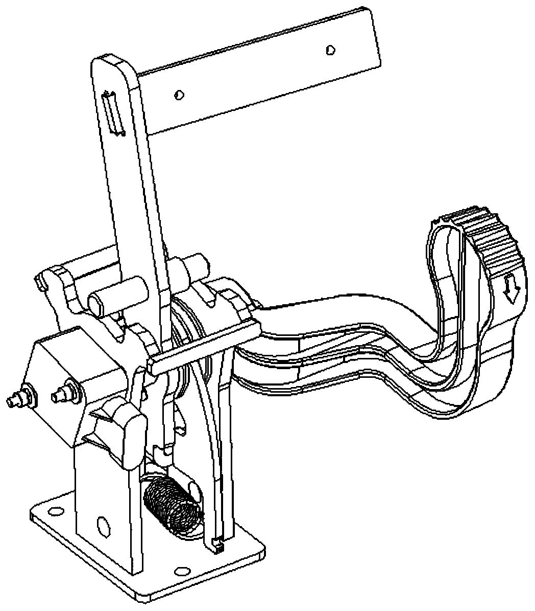
[0024] Such as figure 1 and 2 As shown, a two-way return mechanism of the accelerator pedal is suitable for the accelerator mechanism of vehicles with driving forward and backward functions such as lawn mowers, floor washing machines, ATVs, UTVs, and golf carts. It can also be applied to the accelerator mechanism of electric scooters, electric tricycles, four-wheelers, old scooters, electric vehicles and other slow road electric vehicles.
[0025] The drive shaft 1 has a built-in toggle sensor for sensing the direction of rotation and the range of rotation, and the drive shaft 1 is fitted with a flanged nylon sleeve 2 to increase wear resistance and reduce noise.
[0026] The forward pedal assembly 3 includes: a shaft hole 31 for matching the drive shaft, a pedal end on one side of the shaft hole 31, and a shift fork end 32 on the other side of the shaft hole 31; with the shaft hole 31 as the rotation center, the pedal end is located on the top side, the shift fork end 32 is...
Embodiment 2
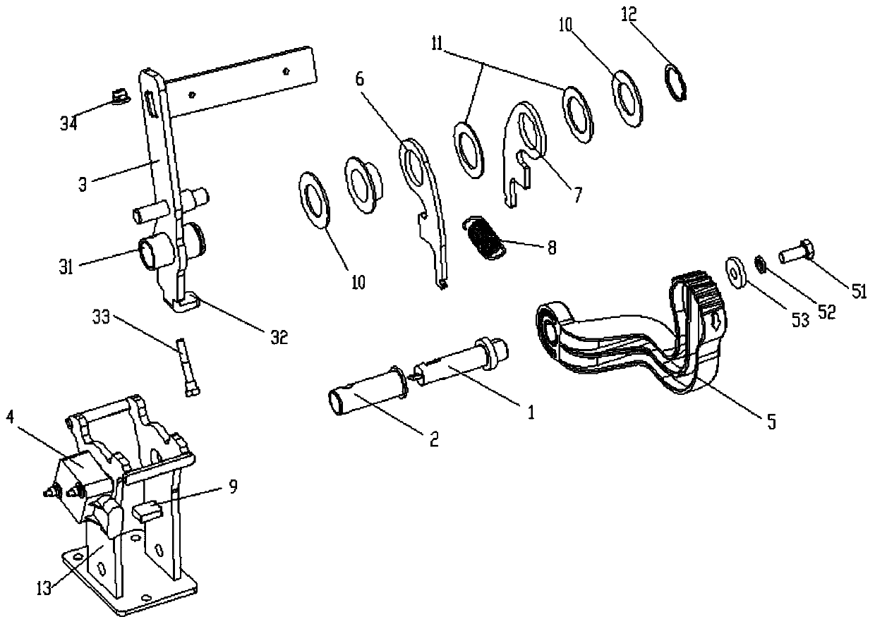
[0033] Such as figure 2 shown.
[0034] 1. The first pull plate 6 and the second pull plate 7 are installed through some reinforced iron pads 10 and nylon pads 11 with wear-resisting and noise-reducing effects, and then installed on the forward accelerator pedal assembly by a circlip 12 for the shaft. On the outer circle of the shaft tube 31 of 3, the two pull plates have no displacement function in the axial direction, and can only rotate freely in the circumferential direction.
[0035] 2. Assemble the assembled semi-finished product to the inside of the external bracket 13, insert the flange nylon bushing 2 and the drive shaft 1 from the outside through the external bracket 13 into the shaft tube 31 of the forward accelerator pedal total 3, and then use a The stepped bolts 33 pass through the axle tube 31, the flange nylon bushing 2, the drive shaft 1, and then the flange nylon bushing, then the axle tube passes through, and lock the nut 34. The flange nylon bushing 2, t...
PUM
 Abstract
Description
Claims
Application Information
 - R&D Engineer
- R&D Manager
- IP Professional
- Industry Leading Data Capabilities
- Powerful AI technology
- Patent DNA Extraction
Browse by: Latest US Patents, China's latest patents, Technical Efficacy Thesaurus, Application Domain, Technology Topic, Popular Technical Reports.
© 2024 PatSnap. All rights reserved.Legal|Privacy policy|Modern Slavery Act Transparency Statement|Sitemap|About US| Contact US: help@patsnap.com