
Device facilitating wheel replacement

A wheel and sliding installation technology, which is applied in the direction of wheel assembly and disassembly equipment, wheel, tire installation, etc., can solve problems such as inconvenient, affecting work efficiency, time-consuming and labor-intensive

Inactive Publication Date: 2020-07-07
刘吉成
View PDF0 Cites 4 Cited by
  • Summary
  • Abstract
  • Description
  • Claims
  • Application Information

AI Technical Summary

Problems solved by technology

[0002] Cars have become the most commonly used means of transportation for people, and the work of car maintenance has also become more and more. The replacement of car tires is common. Most of the existing car tire replacement methods are manual handling operations, which are time-consuming and labor-intensive. The inventors have found that the device for assisting tire replacement in the prior art has many disadvantages, and it is inconvenient during actual use, which affects work efficiency on the contrary.

Method used


Image

  • Device facilitating wheel replacement
  • Device facilitating wheel replacement
  • Device facilitating wheel replacement

Examples


specific Embodiment approach 1

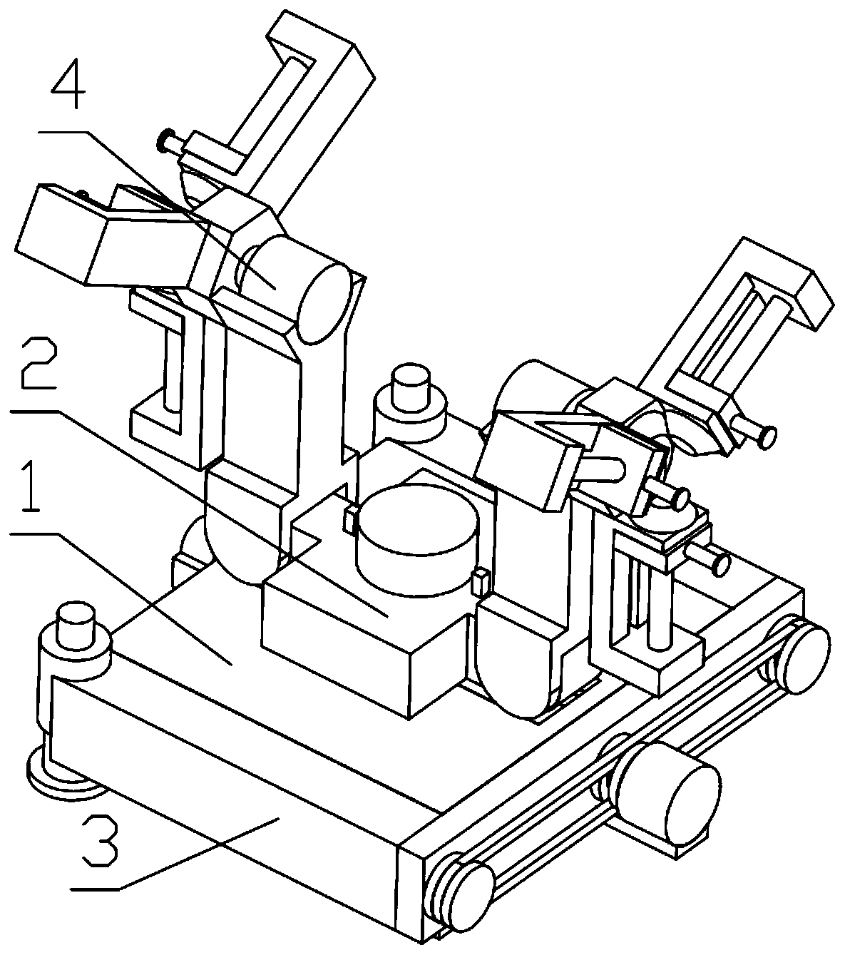
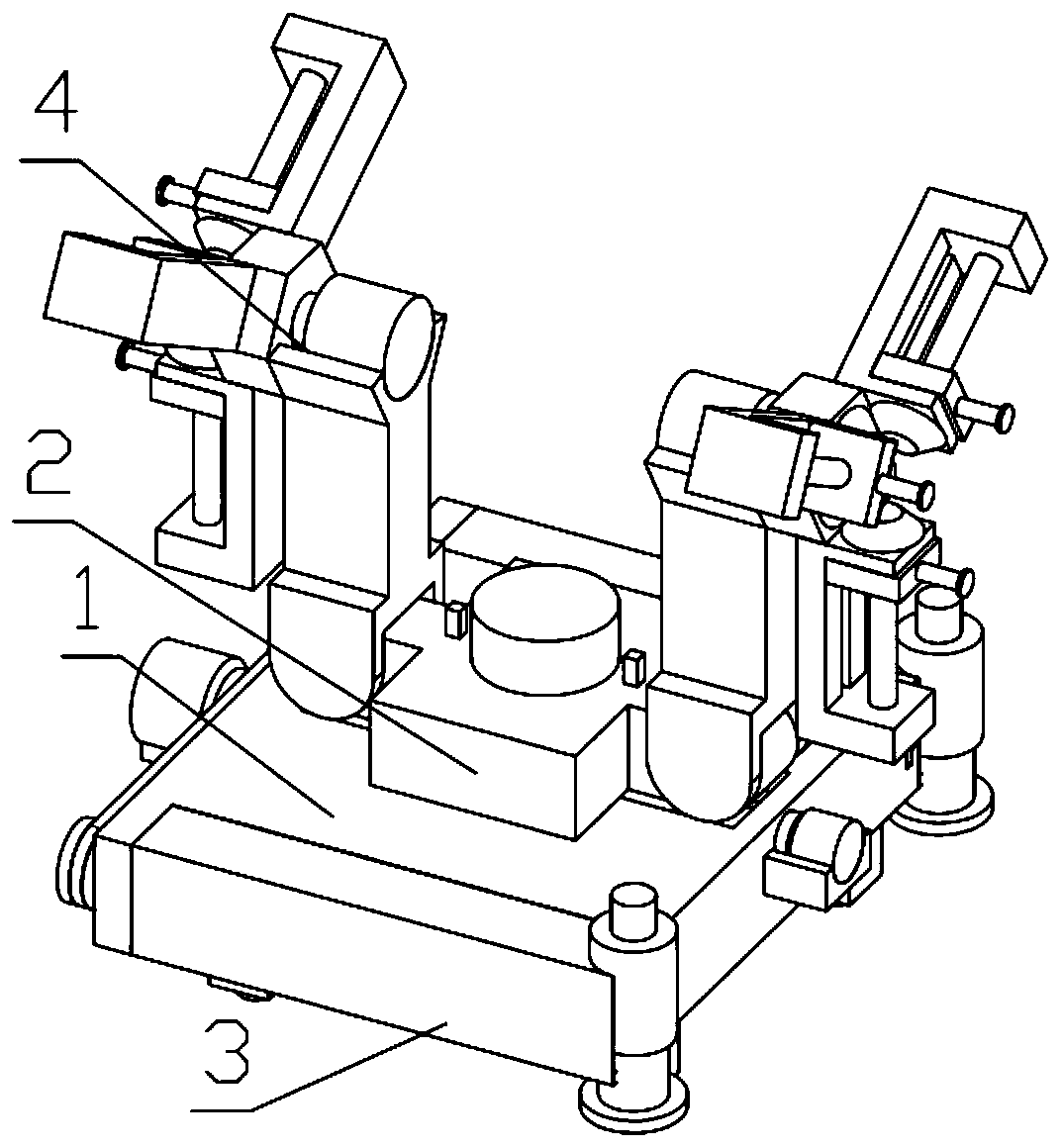
[0035] Combine below Figure 1-13 Description of this embodiment, a device for easy wheel replacement, including a device base 1, the rotating mechanism 2 is installed on the device base 1, the jack mechanism 3 is installed on the device base 1, and the wheel clamping mechanism 4 is installed on the rotating mechanism 2 on.

specific Embodiment approach 2

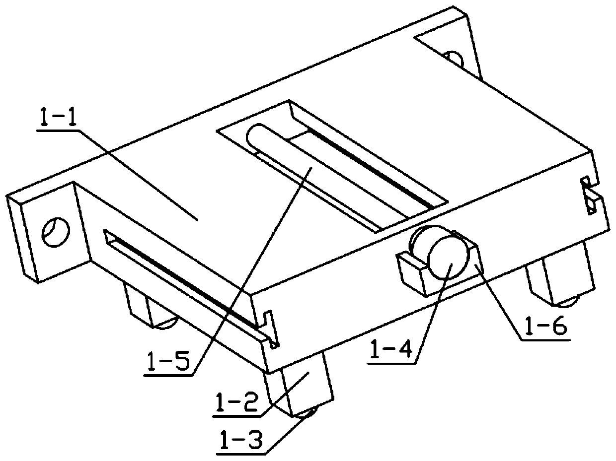
[0037] Combine below Figure 1-13 Describe this embodiment, this embodiment will further explain the first embodiment, the device base 1 includes a base body 1-1, support legs 1-2, universal wheels 1-3, small motor 1-4, threaded rod 1 -5. The motor base 1-6, the motor base 1-6 is fixedly installed on the base body 1-1, the small motor 1-4 is fixedly installed on the motor base 1-6, and the supporting legs 1-2 are fixedly installed on the base body 1 -1, the universal wheel 1-3 is installed on the support leg 1-2, the threaded rod 1-5 is rotatably installed on the groove provided on the base body 1-1, and the threaded rod 1-5 is fixedly installed on the small motor 1 -4 output.

specific Embodiment approach 3

[0039] Combine below Figure 1-13 Describe this embodiment, this embodiment will further explain the second embodiment, the rotating mechanism 2 includes a special-shaped connection shell 2-1, a U-shaped insert 2-2, a resistance rubber ring 2-3, a T-shaped screw 2- 4. Cylindrical piece 2-5, mobile rolling ball 2-6, motor for rotation 2-7, motor output turntable 2-8, internal spring 2-9, one end of internal spring 2-9 is fixedly installed in special-shaped connection shell 2 In the groove provided on -1, the other end of the internal spring 2-9 is fixedly installed on the U-shaped plug-in 2-2, and the U-shaped plug-in 2-2 is slidably installed on the groove provided on the special-shaped connection shell 2-1, The cylindrical part 2-5 is fixedly installed on the T-shaped threaded part 2-4, the mobile rolling ball 2-6 is movably installed in the groove provided on the cylindrical part 2-5, and the rotating motor 2-7 is fixedly installed on the T-shaped screw part. On the shaped ...


PUM


Abstract

The invention relates to an automobile repairing device, in particular to a device facilitating wheel replacement. The device comprises a device base; a rotating mechanism is mounted on the device base; a jack mechanism is installed on the device base; and a wheel clamping mechanism is installed on the rotating mechanism. An automobile can be lifted by the device, so that the tires of the automobile can be conveniently dismounted; the dismounted tires can be moved to the back, tires required to be replaced can be moved to the front, and actual operation can be greatly saved, and work efficiency can be improved.

Description

technical field [0001] The invention relates to a vehicle repair device, more particularly to a device for conveniently changing wheels. Background technique [0002] Cars have become the most commonly used means of transportation for people, and the work of car maintenance has also become more and more. The replacement of car tires is common. Most of the existing car tire replacement methods are manual handling operations, which are time-consuming and labor-intensive. The inventors of the present invention have found that the devices for assisting tire replacement in the prior art have many disadvantages, and are inconvenient during actual use, which instead affects work efficiency. Contents of the invention [0003] The technical problem mainly solved by the present invention is to provide a device for easy wheel replacement. The device can lift the car to facilitate the dismantling of the car tires. To the front, it greatly saves the operation time and improves the wor...

Claims


Application Information

Patent Timeline
IPC IPC(8): B60B29/00
CPCB60B29/001B60B29/002B60B29/008B60B2340/32B60B2340/52B60B2900/521
Inventor 刘吉成
Owner 刘吉成
Learn More