Cleaning device for mechanical engineering part

A cleaning device, a technology of mechanical engineering, applied in the directions of cleaning methods, cleaning methods and utensils, chemical instruments and methods using liquids, etc., can solve the problem of damage to the stirring shaft, difficulty in stirring and cleaning, and increase the cleaning cost of mechanical engineering parts. Cleaning equipment maintenance cost, etc.

Inactive Publication Date: 2020-07-07
刘京標
View PDF1 Cites 0 Cited by
  • Summary
  • Abstract
  • Description
  • Claims
  • Application Information

AI Technical Summary

Problems solved by technology

[0006] The purpose of the present invention is to provide a cleaning device for mechanical engineering parts, to solve the problem that although the parts are always immersed in the cleaning liquid in the cylinder body and rotate under the drive of the central shaft, it is beneficial to The dirt on the parts is washed away, the cleaning effect is good, and the cleaning efficiency is high. However, because most of the mechanical engineering parts are made of steel and have a large mass, it is difficult to stir and clean them through the stirring shaft, which affects the mechanical engineering parts. At the same time, it is easy to cause damage to the stirring shaft due to the mutual connection between mechanical engineering parts, which increases the cost of cleaning mechanical engineering parts and the cost of cleaning equipment maintenance in the later period.

Method used


Image

  • Cleaning device for mechanical engineering part
  • Cleaning device for mechanical engineering part
  • Cleaning device for mechanical engineering part

Examples


Embodiment Construction

[0020] The following will clearly and completely describe the technical solutions in the embodiments of the present invention with reference to the accompanying drawings in the embodiments of the present invention. Obviously, the described embodiments are only some, not all, embodiments of the present invention. Based on the embodiments of the present invention, all other embodiments obtained by persons of ordinary skill in the art without creative efforts fall within the protection scope of the present invention.

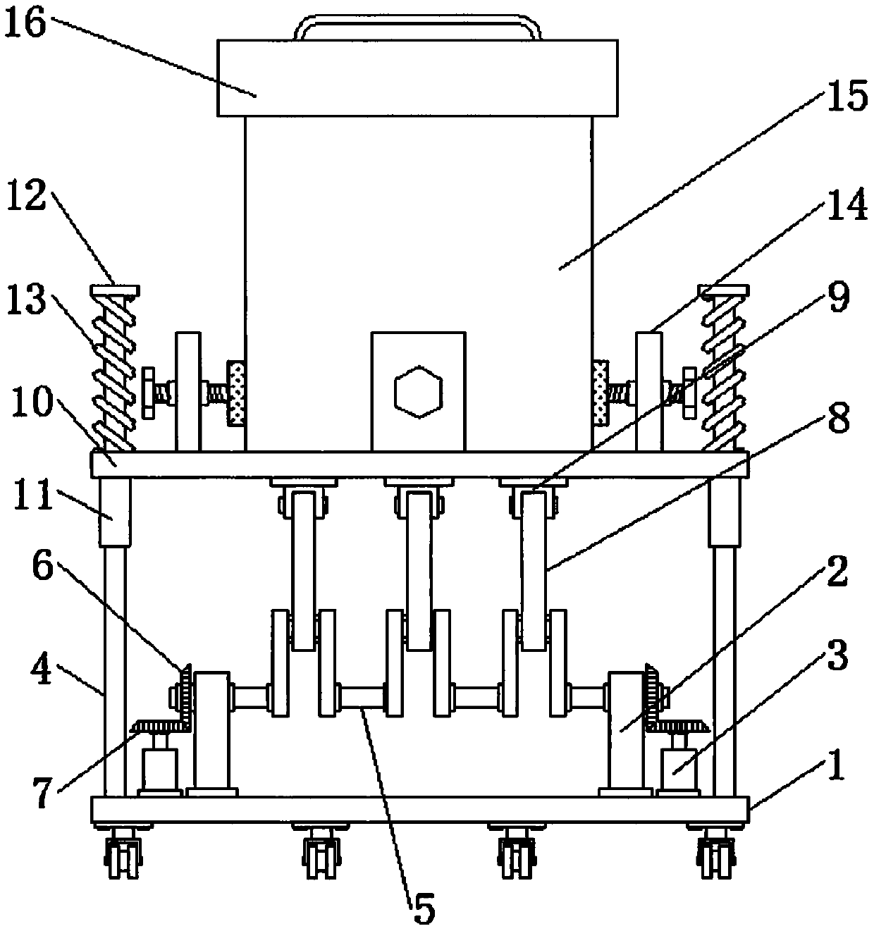
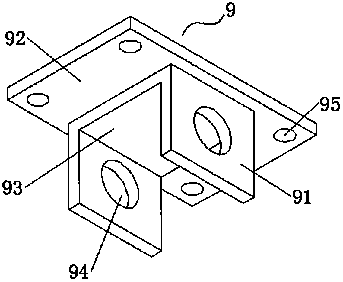
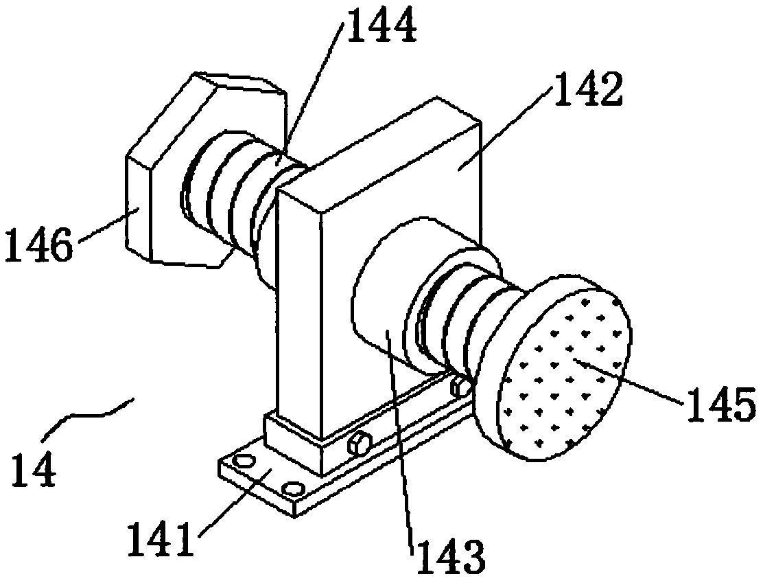
[0021] see Figure 1-3 , the present invention provides a technical solution: a cleaning device for mechanical engineering parts, including a support base plate 1, two sets of support side plates 2, two sets of drive motors 3 and two sets of stable Slide bar 4, and two groups of support side plates 2 and two groups of driving motors 3 are arranged between two groups of stable slide bars 4, and transmission crankshaft 5 is installed laterally through rotating bearin...


PUM


Abstract

The invention discloses a cleaning device for a mechanical engineering part in the technical field of mechanical engineering. The cleaning device comprises a supporting bottom plate, wherein two groups of supporting side plates, two groups of driving motors and two groups of stable sliding rods are symmetrically arranged at the top of the supporting bottom plate, and the two groups of supporting side plates and the two groups of driving motors are arranged between the two groups of stable sliding rods; and a transmission crankshaft is transversely installed between the two groups of supportingside plates through a rotating bearing and penetrates through the supporting side plates. According to the cleaning device, the mechanical engineering part and washing liquid are placed in an inner cavity of a cleaning barrel, the cleaning barrel is sealed through a sealing end cover, then a driving motor is controlled to be started through a control switch, and through a series of mechanical transmission, a supporting sliding plate can move up and down under limitation of the stable sliding rods, so that the mechanical engineering part and the washing liquid in the inner cavity of the washing barrel collide with each other due to the up-down movement of the supporting sliding plate, and then the mechanical engineering part is washed.

Description

technical field [0001] The invention relates to the technical field of mechanical engineering, in particular to a cleaning device for mechanical engineering parts. Background technique [0002] Mechanical engineering has always been researching and developing new mechanical products with the goal of increasing production, improving labor productivity, and improving the economy of production, that is, to improve human interests. In the future era, the development of new products will reduce resource consumption, develop clean renewable energy, control, reduce and even eliminate environmental pollution as super-economic goals. Mechanical engineering involves a large number of parts, and the cleaning of parts is a mechanical engineering An indispensable link in production, due to the various forms of mechanical parts, it is difficult to clean. The existing cleaning automation of mechanical engineering parts is low, and the cleaning efficiency is not high. [0003] For example...

Claims


Application Information

Patent Timeline
IPC IPC(8): B08B3/10B08B3/08B08B13/00
CPCB08B3/08B08B3/10B08B13/00
Inventor 刘京標
Owner 刘京標
Why Eureka
Try Eureka