Ceiling-mounted indoor unit for air conditioner

A ceiling and indoor unit technology, applied in air conditioning systems, heating methods, mechanical equipment, etc., can solve problems such as difficulty in satisfying indoor personnel

Active Publication Date: 2020-07-03
LG ELECTRONICS INC
View PDF16 Cites 0 Cited by
  • Summary
  • Abstract
  • Description
  • Claims
  • Application Information

AI Technical Summary

Problems solved by technology

[0014] Therefore, in the ceiling-type indoor unit of the prior art, when heating the room, there is a problem that it is difficult to meet the needs of the people in the room due to the simple control of the discharge blades.

Method used


Image

  • Ceiling-mounted indoor unit for air conditioner
  • Ceiling-mounted indoor unit for air conditioner
  • Ceiling-mounted indoor unit for air conditioner

Examples


Embodiment Construction

[0090] The advantages, features, and methods for realizing the present invention can be clarified more clearly by referring to the accompanying drawings and the embodiments described in detail later. However, the present invention is not limited to the embodiments disclosed below, but can be realized in various forms. This embodiment is only for more complete disclosure of the present invention, so as to clarify to those of ordinary skill in the technical field to which the present invention belongs. The scope of the present invention is fully shown, and the present invention is defined only by the scope of the claims. Throughout the specification, the same reference numerals denote the same structural elements.

[0091] The present invention will be specifically described below with reference to the accompanying drawings.

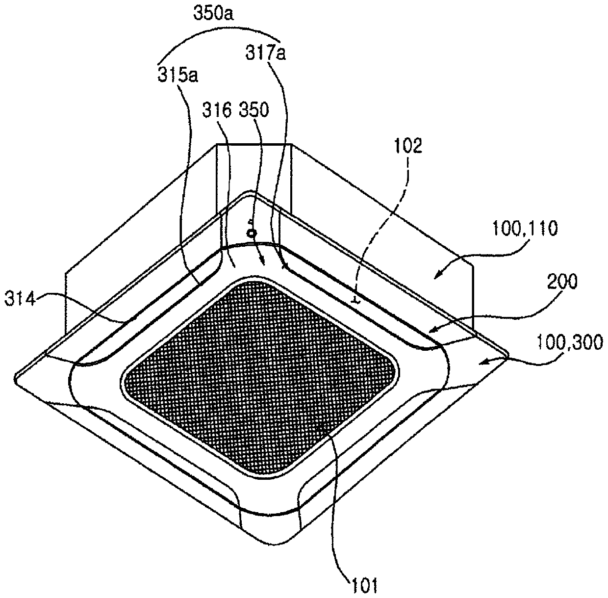
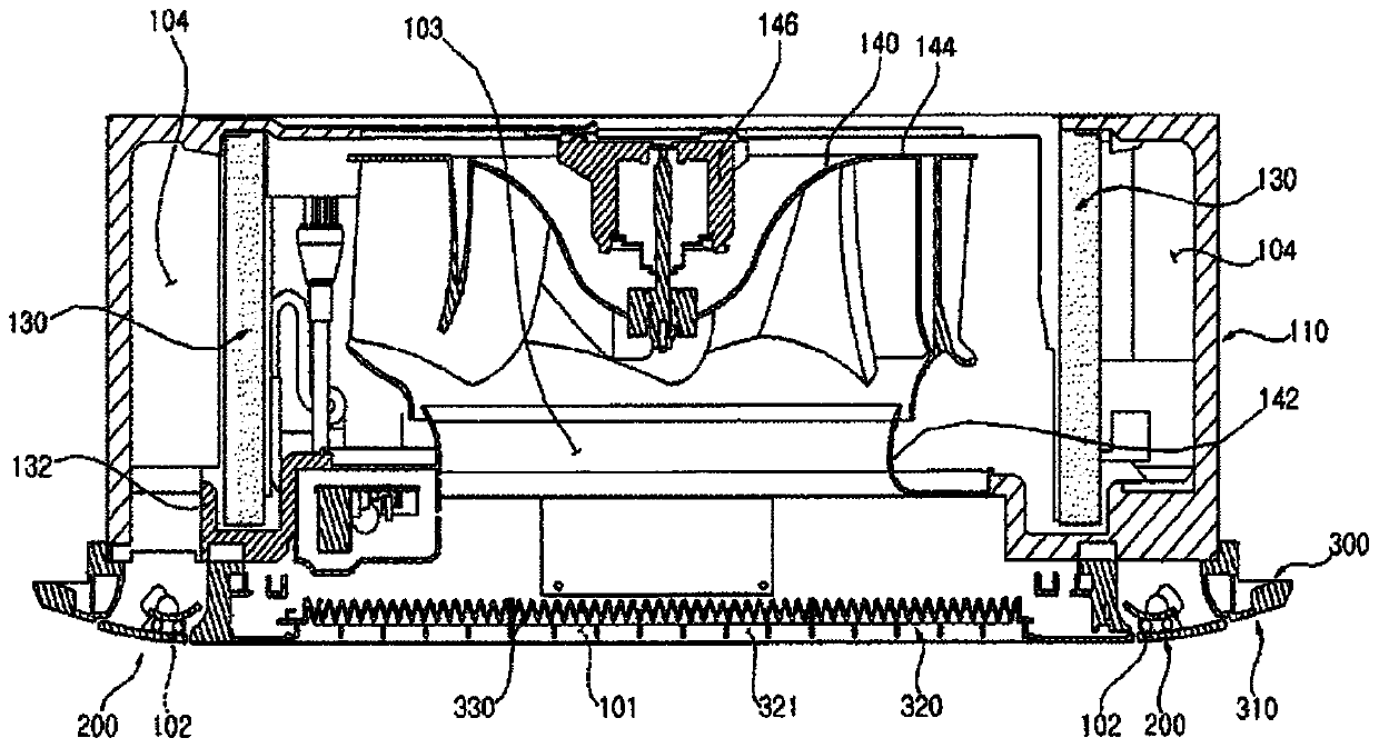
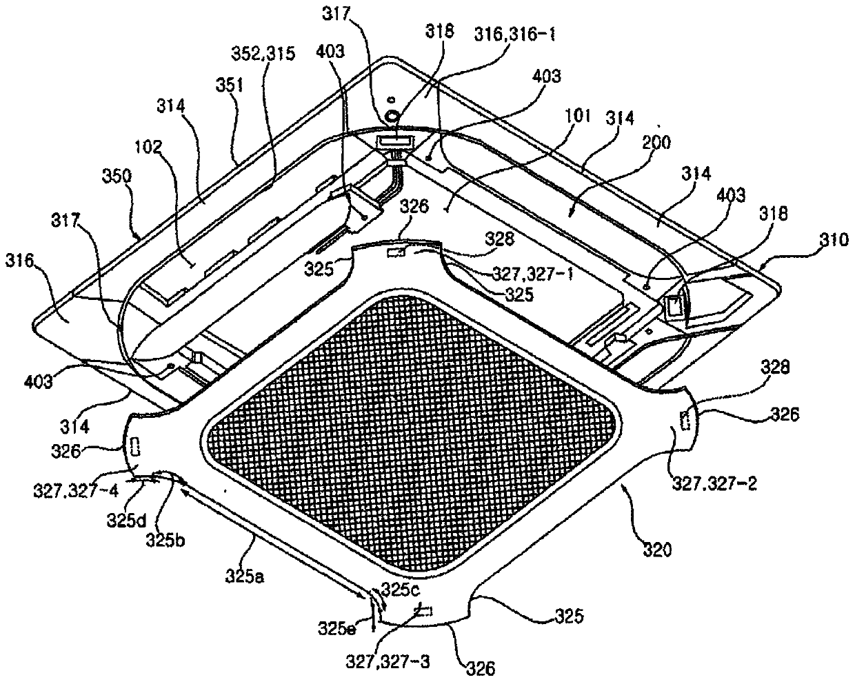
[0092] figure 1 It is a perspective view showing an air conditioner indoor unit according to an embodiment of the present invention. figure 2 yes fig...


PUM


Abstract

The present invention has four vane modules, two of the vane modules facing each other and forming a first discharge pair and the remaining two forming a second discharge pair. The first discharge pair and the second discharge pair provide indirect wind and direct wind in alternation, and thus an indoor space can be heated quickly. The first discharge pair and the second discharge pair discharge air at different angles from each other, and thus the blind spots to which the discharged air does not reach can be minimized.

Description

technical field [0001] The present invention relates to a control method of a ceiling-type indoor unit of an air conditioner, and more specifically relates to a control method of a ceiling-type indoor unit related to the first, second, third and fourth blade modules during indoor heating. Background technique [0002] Generally speaking, an air conditioner consists of a compressor, condenser, evaporator, expander, and uses the air conditioning cycle to supply cold or hot air to a building or room. [0003] Structurally, the air conditioner is divided into a split type in which the compressor is arranged outdoors and an integrated type in which the compressor is manufactured in an integrated manner. [0004] In the split type, an indoor heat exchanger is installed in the indoor unit, an outdoor heat exchanger and a compressor are installed in the outdoor unit, and the two separate devices are connected by refrigerant piping. [0005] The integrated type is to arrange the ind...

Claims


Application Information

Patent Timeline
Patent Type & Authority Applications(China)
IPC IPC(8): F24F13/14F24F1/0047F24F11/64F24F11/65F24F11/79
CPCF24F13/14F24F1/0011F24F1/0047F24F13/1413F24F2013/1433F24F13/06F24F11/79F24F11/65F24F2221/54F24F11/61F24F13/1426
Inventor 李秀贞尹炯男
Owner LG ELECTRONICS INC
Why Eureka
Try Eureka