
Linear power machine and power tool

A linear, dynamic machine technology, applied in the direction of reciprocating/oscillating/vibrating magnetic circuit components, electromechanical devices, electric components, etc., can solve the problem that the mover damages the stator, eats, the track or guide structure increases the overall structural size chain, etc. Problems, achieve the effect of reducing friction, reducing wear and heat, improving heat dissipation efficiency and heat dissipation effect

Pending Publication Date: 2020-07-03
苏州品匠机电技术有限公司
View PDF2 Cites 8 Cited by
  • Summary
  • Abstract
  • Description
  • Claims
  • Application Information

AI Technical Summary

Problems solved by technology

[0004] At the same time, the mover of a conventional linear motor needs to slide on a certain track or guide structure. The biggest problem with this structure is that the track or guide structure increases the dimensional chain of the overall structure, resulting in higher manufacturing precision requirements. The mover and stator The air between them is easy to be eaten by the tolerance band, and it is easy to cause the problem that the mover hurts the stator

Method used


Image

  • Linear power machine and power tool
  • Linear power machine and power tool
  • Linear power machine and power tool

Examples


Embodiment Construction

[0043]Objects, advantages and features of the present invention will be illustrated and explained by the following non-limiting description of preferred embodiments. These embodiments are only typical examples of applying the technical solutions of the present invention, and all technical solutions formed by adopting equivalent replacements or equivalent transformations fall within the protection scope of the present invention.

[0044] In the description of the scheme, it should be noted that the terms "center", "upper", "lower", "left", "right", "front", "rear", "vertical", "horizontal", " The orientation or positional relationship indicated by "inner", "outer", etc. is based on the orientation or positional relationship shown in the drawings, and is only for the convenience of description and simplification of description, rather than indicating or implying that the device or element referred to must have a specific orientation , constructed and operated in a particular ori...


PUM


Abstract

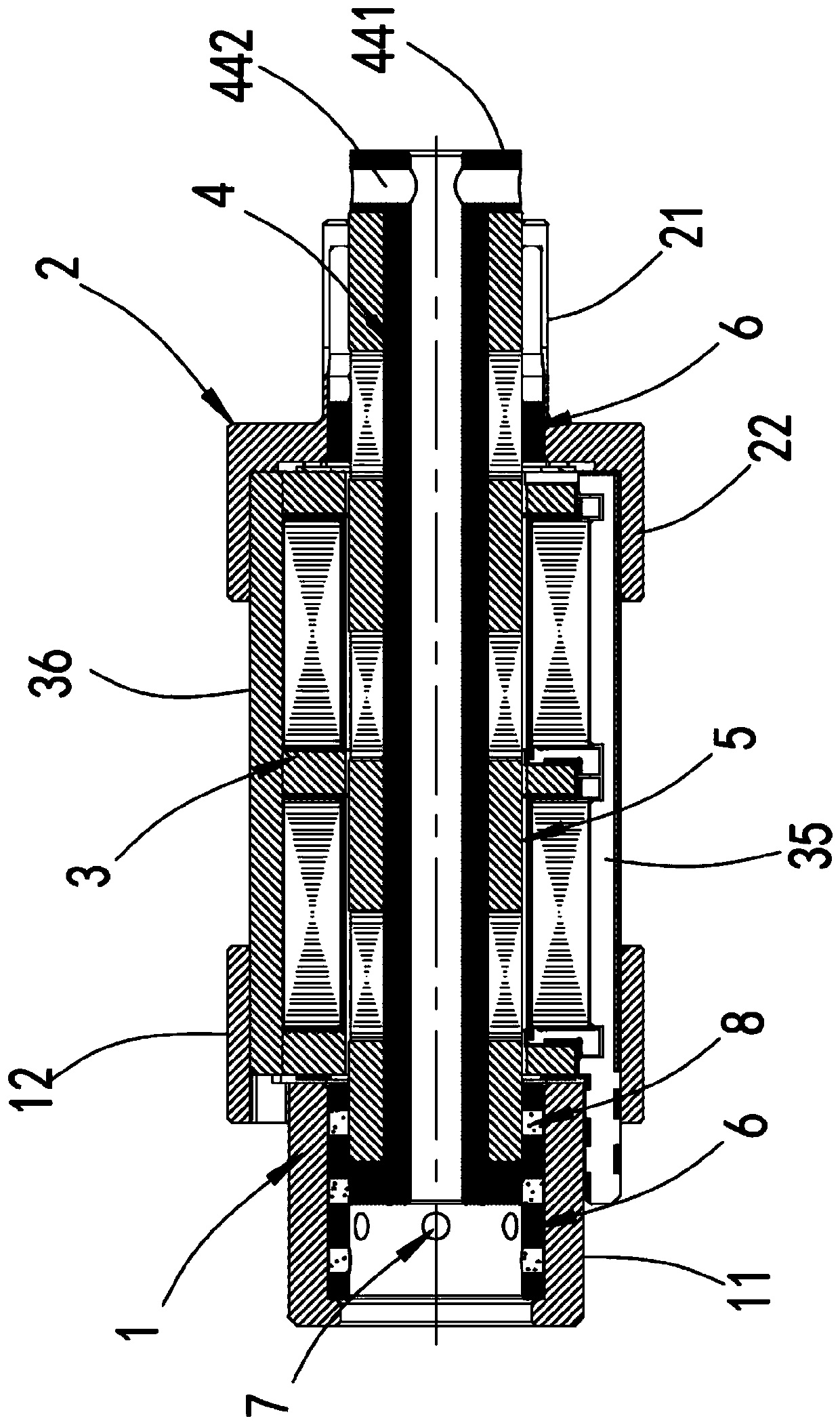
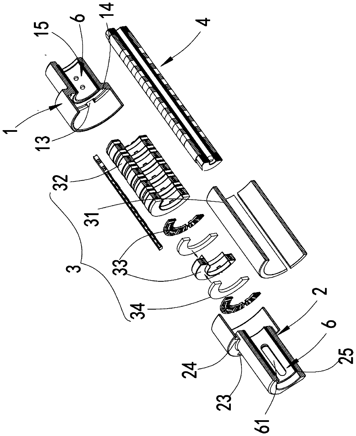
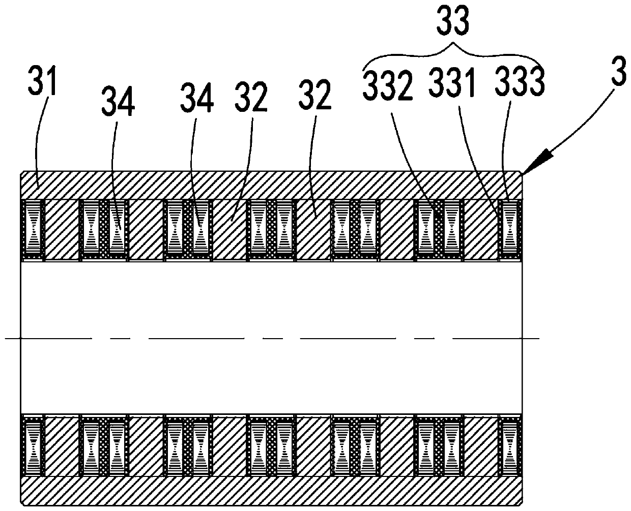
The invention discloses a linear power machine and a power tool. The linear power machine enables the stator component to be installed on the first end and the second end. The mover component is guided and supported by the first end and the second end. No extra guide rail or guide structure is needed to be matched with the mover component. The whole structure is simplified, the size chain of the motor is reduced, the problem that the rotor component and the stator component are damaged by collision due to tolerance is avoided, the requirement for the precision of the components is lowered accordingly, the manufacturing difficulty is lowered, the precision of the motor is improved, and under the condition of the same size, the driving force of the scheme is larger, and the effect is better.Meanwhile, the stator component is partially exposed, heat exchange with external air can be effectively carried out through the exposed area of the stator component to achieve heat dissipation, andthe heat dissipation efficiency is improved.

Description

technical field [0001] The invention relates to the field of motors, in particular to linear power machines and power tools, more specifically to electric-driven tools, especially hand-held electric tools. Background technique [0002] At present, most of the reciprocating motions in the power tool market are realized by rotary motors and conversion mechanisms. There are several problems in this way. low, the cost becomes high. [0003] Linear motor is a transmission device that directly converts electrical energy into linear motion mechanical energy without any intermediate conversion mechanism. Various linear motors commonly used in the market adopt the structure disclosed by the application numbers 201711454263.X and 201820182974.X. This structure has high cost, relatively large size and low power. For power tools with small installation space, especially Cannot be used effectively by hand. Therefore, it is urgently needed for the field of power tools, especially for v...

Claims


Application Information

Patent Timeline
IPC IPC(8): H02K41/02H02K33/00H02K9/00H02K3/32H02K3/46H02K1/12H02K1/16H02K1/34H02K29/00
CPCH02K1/12H02K1/16H02K1/34H02K3/32H02K3/46H02K9/00H02K29/00H02K33/00H02K41/02
Inventor 张涛丁学明胡方坤朱学超
Owner 苏州品匠机电技术有限公司
Learn More