Connecting structure of pipe assembly

A connection structure and pipe material technology, which is applied in the direction of hose connection device, sleeve/socket connection, pipe/pipe joint/pipe fitting, etc., can solve the problems of poor sealing effect, high engineering cost, and pipe disengagement, etc. Reliable performance, long service life, and the effect of maintaining stability

Pending Publication Date: 2020-07-03
萍乡市大地新材料科技有限公司
View PDF0 Cites 0 Cited by
  • Summary
  • Abstract
  • Description
  • Claims
  • Application Information

AI Technical Summary

Problems solved by technology

In this connection method, due to the elasticity of the sealing ring, the sealing ring will drive the axial rebound of the pipe after insertion, which will make the sealing effect worse. In addition, due to geological subsidence in the later stage, it will generate tension on the pipe and make the pipe disengage.
The flange connection method requires many connection parts such as flanges and bolt assemblies, which is troublesome to install and high in engineering cost.

Method used


Image

  • Connecting structure of pipe assembly
  • Connecting structure of pipe assembly
  • Connecting structure of pipe assembly

Examples


Embodiment 1

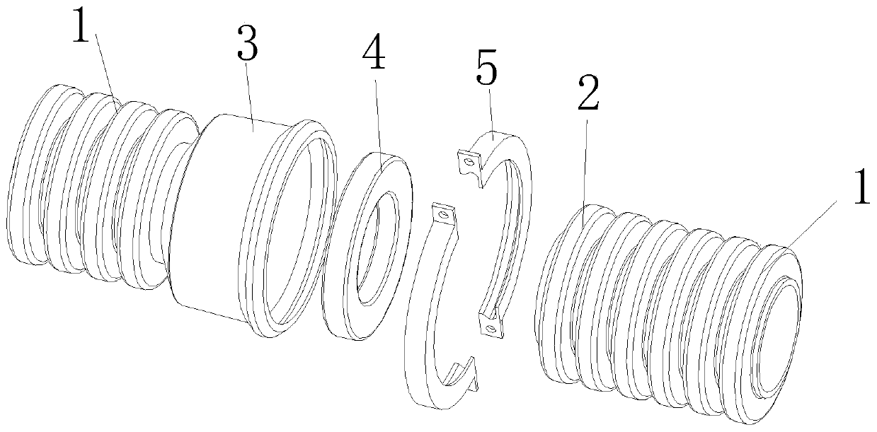
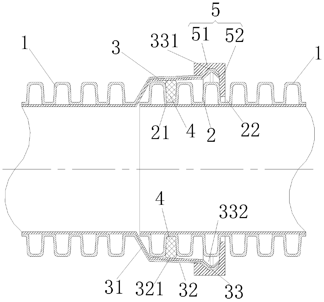
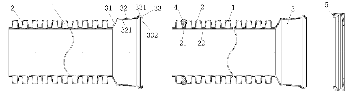
[0031] A connection structure of pipe components in the present invention is characterized in that it includes at least two pipes 1; one end port of one pipe 1 is fixedly connected with a tubular socket section 2, and one end port of the other pipe 1 is fixed A tubular socket section 3 is connected to fit with the socket section 2, and the connection structure of the pipe assembly also includes a sealing ring 4 arranged between the outer peripheral wall of the socket section 2 and the inner peripheral wall of the socket section 3 and buckled The buckle 5 between the outer peripheral wall of the socket section 3 and the outer peripheral wall of the socket section 2;

[0032] The outer peripheral wall of the socket section 2 is provided with a sealing ring installation groove 21 for installing the sealing ring 4 and a buckle fitting groove 22 for snapping the buckle 5 arranged around the outer peripheral wall, and the sealing ring The installation groove 21 is located close to t...

Embodiment 2

[0045] The difference between this embodiment and the first embodiment is that: preferably, the number of the outer flanges 331 is more than two, and each outer flange 331 is distributed sequentially and at intervals along the same circumferential direction around the axis. The groove provided on the inner peripheral wall of the buckle body 51 is adapted to the shape, size and position of the outer flange. The corresponding socket fits the groove of the edge. Each of the anti-off bodies 52 can be arranged in an annular closed manner along the same circumferential direction around the axis, or arranged at intervals in sequence; the sum of the arcs that each of the anti-off bodies 52 extend along the same circumferential direction around the axis can be less than or equal to 360 °.

Embodiment 3

[0047] The difference between this embodiment and the first embodiment is that: preferably, the first tapered sealing section 321 of the inner peripheral wall of the sealing receiving section 32 extends outward along the taper to the outer port of the socket section 3 .


PUM


Abstract

The invention relates to a connecting structure of a pipe assembly. The connecting structure comprises at least two pipes, wherein a spigot section is connected to one of the pipes, a socket section is connected to the other pipe, and a seal ring and a clamping buckle part are also configured; a seal ring installation groove and a clamping groove of the clamping buckle part are formed in the spigot section; the socket section comprises a clamping section, a seal bearing section and a linkage section; an outer flange is disposed on the clamping section; and the clamping buckle part comprises aclamping buckle body and an anti-stripping body, the anti-stripping body can be stretched into the clamping groove of the clamping buckle part and is buckled and pressed on a groove side wall, close to the side of an outer port of the spigot section, of the clamping groove of the clamping buckle part. The connecting structure provided by the invention has the beneficial effects that after the spigot section is inserted in place relative to the socket section, the seal bearing section can be closely fitted with the seal ring, and the seal bearing section is buckled and pressed on the side wallof the clamping groove of the clamping buckle part by the anti-stripping part of the clamping buckle part, so that the spigot section cannot be stripped out relative to the socket section, the seal ring is effectively prevented from driving axial rebounding of the pipes, the pipes do not get stripped even in case of geological sedimentation in a later stage, and the service life is long.

Description

technical field [0001] The invention relates to the field of pipes, in particular to a connection structure of pipe components. Background technique [0002] Bellows are widely used in the field of drainage due to their good compression resistance, low engineering cost, light weight, and quick and convenient construction. For the convenience of transportation, the length of each section of bellows cannot be made too long, and they are all connected when they are transported to the construction site for installation. The connection mode of the existing bellows is generally a plug-in type or a flange connection type. The plug-in connection method is: install a rubber sealing ring at the second trough of the socket end and apply lubricant, then directly insert the socket, and pay attention to the socket should be against the direction of water flow, and the socket should follow the direction of water flow. In this connection method, due to the elasticity of the sealing ring, ...

Claims


Application Information

Patent Timeline
Patent Type & Authority Applications(China)
IPC IPC(8): F16L21/02F16L21/06F16L9/00F16L11/15F16L33/02
CPCF16L9/00F16L11/15F16L21/02F16L21/06F16L33/02
Inventor 周成纤
Owner 萍乡市大地新材料科技有限公司
Why Eureka
Try Eureka