Multi-angle lubricating device for injection molding machine and working method thereof

A technique of lubricating device and working method, which is applied in the field of lubricating devices, can solve the problems of inaccurate position, time-consuming and labor-intensive use, and small range, and achieve the effects of high safety, improved universality, and avoiding accidental injuries

Active Publication Date: 2022-01-11
重庆安丰塑胶科技有限公司
View PDF7 Cites 0 Cited by
  • Summary
  • Abstract
  • Description
  • Claims
  • Application Information

AI Technical Summary

Problems solved by technology

[0004] The purpose of the present invention is to solve the inaccurate position of the lubricating device for the existing injection molding machine to lubricate the parts on the injection molding machine, and can only lubricate the injection molding machine with the same height and width, and the lubricating device works properly. The distribution range is small; and when the existing lubricating device is in use, the transmission parts at the bottom of the lubricating table are easy to be scratched and damaged by external objects when they are working, and the transmission parts at the bottom of the lubricating table are easy to rub against the human body during work. Injury; and the oil outlet cylinder on the lubricating device can be adjusted up and down in a small range; the area covered by the lubricating device for lubricating the parts on the injection molding machine is not comprehensive enough; the staff cannot adjust the lubrication in accordance with the lubrication needs of different injection molding machines The number of oil outlet tubes installed on the device is not flexible enough to use; the automation of the lubricating device is low, and the use of time-consuming and labor-intensive problems, and a multi-angle lubricating device for injection molding machines and its working method are proposed

Method used


Image

  • Multi-angle lubricating device for injection molding machine and working method thereof
  • Multi-angle lubricating device for injection molding machine and working method thereof
  • Multi-angle lubricating device for injection molding machine and working method thereof

Examples


Embodiment Construction

[0044] The technical solutions of the present invention will be clearly and completely described below in conjunction with the embodiments. Apparently, the described embodiments are only some of the embodiments of the present invention, not all of them. Based on the embodiments of the present invention, all other embodiments obtained by persons of ordinary skill in the art without creative efforts fall within the protection scope of the present invention.

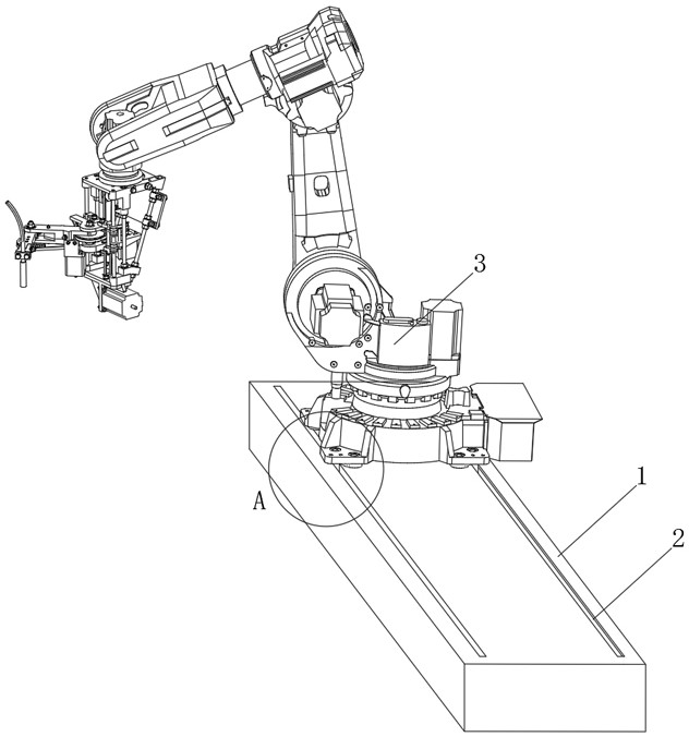
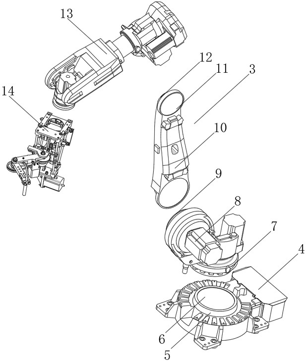
[0045] see Figure 1-10 As shown, a multi-angle lubricating device for an injection molding machine includes a sleeve 1 and a lubricating table 3, and the sleeve 1 is horizontally arranged on the lubricating table 3;

[0046] The bottom of the lubricating table 3 is provided with a bottom moving frame 4, and the inside of the bottom moving frame 4 is vertically provided with a motor one 5, and the upper part of the motor one 5 is connected with the lower rotating frame 7 through the rotation of the rotating shaft one 6, and...


PUM


Abstract

The invention discloses a multi-angle lubricating device for an injection molding machine and a working method thereof. Motor 1 is vertically sleeved inside the moving frame, and the upper part of the motor 1 is connected to the lower rotating frame through the rotation of the rotating shaft 1, and the motor 2 is horizontally sleeved above the lower rotating frame, and one end of the motor 2 is rotated through the rotating shaft 2. Attached to the side swing frame. The beneficial effects of the present invention are: motor eight drives the lubricating table to adjust back and forth, and cooperates with motor three to drive the top swing frame and the swing mechanism to swing upwards through the rotating shaft three, and the oil guide tube is placed above the injection molding machine. On the one hand, the oil guide tube is guaranteed to be The position of the injection molding machine that needs to be lubricated for lubricating work is more precise. On the other hand, it is ensured that the device can perform lubrication work on injection molding machines of different heights, which improves the adaptability of the device.

Description

technical field [0001] The invention relates to a lubricating device, in particular to a multi-angle lubricating device for an injection molding machine and a working method thereof, belonging to the application technical field of the lubricating device for an injection molding machine. Background technique [0002] The lubricating device is used more and more frequently during the maintenance of the injection molding machine. The main function of the lubricating device is to add lubricating oil to the parts that are marked on the injection molding machine that are consumable and easy to wear, so as to ensure that the parts on the injection molding machine It is smoother during working activities, improving the working life and flexibility of the injection molding machine. [0003] The existing lubricating device for injection molding machine still has many deficiencies in use. The position of the existing lubricating device for injection molding machine to lubricate the par...

Claims


Application Information

Patent Timeline
Patent Type & Authority Patents(China)
IPC IPC(8): B29C45/83B29C45/84B29C45/17
CPCB29C45/83B29C45/84B29C45/17
Inventor 不公告发明人
Owner 重庆安丰塑胶科技有限公司
Why Eureka
Try Eureka