A mobile feeding mechanism for injection molding machine and its working method

An injection molding machine, mobile technology, applied in the field of feeding mechanism, can solve the problems of poor stability of feeding mechanism, splash environment, poor safety, etc., and achieve the effect of improving feeding quality, high capacity and improving efficiency

Active Publication Date: 2021-12-24
嘉兴市维尔塑业有限公司
View PDF7 Cites 0 Cited by
  • Summary
  • Abstract
  • Description
  • Claims
  • Application Information

AI Technical Summary

Problems solved by technology

[0004] The purpose of the present invention is to solve the problem that the existing feeding mechanism can only feed injection molding machines with the same height, shape and width, and the adaptability range of the work is small; and the feeding cylinder on the feeding mechanism moves to the injection molding machine The efficiency of feeding above the hopper is slow; the accuracy of the feeding mechanism for feeding is low; the feeding mechanism can only accommodate the same material for feeding, and when feeding different injection molding machines, it cannot be flexible and fast. type; and the loading capacity of the feeding mechanism for the material is low; the connection and installation or disassembly of the feeding barrel and the material box on the feeding mechanism is not convenient enough; during the feeding process of the feeding mechanism to the injection molding machine, the material is easy to shake off and splash into the injection molding Environmental pollution caused by the outside of the machine, the stability of the feeding mechanism is poor; and the safety of the feeding mechanism is poor when used, and a mobile feeding mechanism and its working method for injection molding machines are proposed

Method used


Image

  • A mobile feeding mechanism for injection molding machine and its working method
  • A mobile feeding mechanism for injection molding machine and its working method
  • A mobile feeding mechanism for injection molding machine and its working method

Examples


Embodiment Construction

[0044] The technical solutions of the present invention will be clearly and completely described below with reference to the embodiments. Obviously, the described embodiments are only a part of the embodiments of the present invention, rather than all the embodiments. Based on the embodiments of the present invention, all other embodiments obtained by those of ordinary skill in the art without creative efforts shall fall within the protection scope of the present invention.

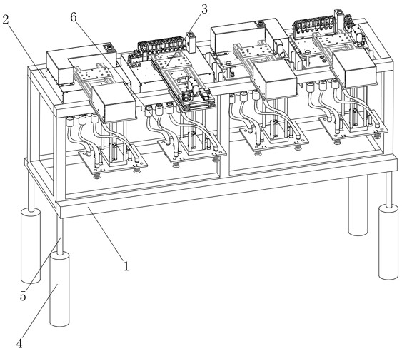
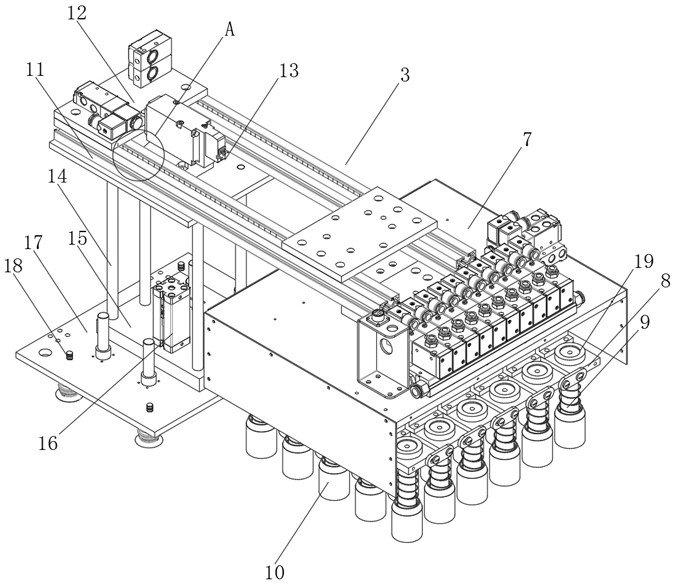
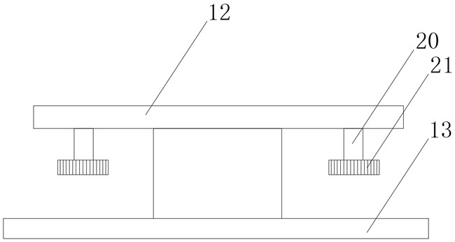
[0045] see Figure 1-11 As shown, a mobile feeding mechanism for an injection molding machine includes a horizontally arranged transmission carrier 1, a sleeve support frame 2 and a hanging table 3, the sleeve support frame 2 is arranged above the transmission carrier 1, and the transmission carrier 1. The bottom is a rectangular structure, and the bottom four corners of the transmission carrier 1 are vertically provided with hydraulic cylinders 4, and the upper part of the hydraulic cylinders 4 is vertic...


PUM


Abstract

The invention discloses a mobile feeding mechanism for an injection molding machine and its working method, which comprises a horizontally arranged transmission carrier, a sleeve support frame and a mounting platform, the sleeve support frame is arranged above the transmission support frame, and the The bottom of the transmission carrier has a rectangular structure, and hydraulic cylinders are arranged vertically under the four corners of the bottom of the transmission carrier. The beneficial effects of the present invention are: the motor 3 on the transmission carrier drives the sleeve support frame to adjust left and right through the gear 3, and cooperates with the motor 1 on the mounting platform to roll in the rolling groove through the gear to drive the feeding cylinder to adjust forward and backward, and The motor 2 drives the rotating carrier plate and the feeding cylinder to rotate and adjust the position through the gear 2. On the one hand, it ensures that the feeding mechanism can feed injection molding machines with different heights, widths and shapes. On the other hand, it ensures that the feeding cylinder moves to the top of the hopper. It is more efficient, and ensures that the mechanism has higher precision in feeding the injection molding machine, and improves the feeding quality of the feeding mechanism.

Description

technical field [0001] The invention relates to a feeding mechanism, in particular to a mobile feeding mechanism for an injection molding machine and a working method thereof, belonging to the technical field of application of the feeding mechanism. Background technique [0002] After the injection molding machine is used for a period of time, the feeding mechanism needs to add injection materials to the hopper of the injection molding machine to ensure the normal injection molding process of the injection molding machine. [0003] The existing feeding mechanism for injection molding machines still has many deficiencies in use. The existing feeding mechanism can only feed injection molding machines of the same height, shape, and width, and the range of adaptability of the work. It is small, and the efficiency of moving the feeding barrel 18 on the feeding mechanism to the top of the hopper of the injection molding machine for feeding is slow, the accuracy of the feeding work...

Claims


Application Information

Patent Timeline
Patent Type & Authority Patents(China)
IPC IPC(8): B29C45/18B29C45/17
CPCB29C45/1858B29C45/1866B29C45/17
Inventor 不公告发明人
Owner 嘉兴市维尔塑业有限公司
Why Eureka
Try Eureka