
Cleaning and maintaining device for construction equipment

A technology for construction and equipment, applied in the field of cleaning and maintenance devices for construction equipment, can solve the problems of disproportion between effort and harvest, easy to miss points in cleaning, poor cleaning and maintenance effect, etc., so as to improve cleaning and maintenance effect and reduce work amount, the effect of accelerating the drying speed

Inactive Publication Date: 2020-07-03
葛飞月
View PDF8 Cites 3 Cited by
  • Summary
  • Abstract
  • Description
  • Claims
  • Application Information

AI Technical Summary

Problems solved by technology

[0004] When cleaning and maintaining equipment based on the existing cleaning and maintenance devices for construction equipment, single-point cleaning requires a large amount of work, and it is easy to miss points during cleaning. The effort and harvest are not proportional, and the cleaning and maintenance effect is still poor. , the present invention proposes a cleaning and maintenance device for building construction equipment

Method used


Image

  • Cleaning and maintaining device for construction equipment
  • Cleaning and maintaining device for construction equipment
  • Cleaning and maintaining device for construction equipment

Examples


Embodiment 1

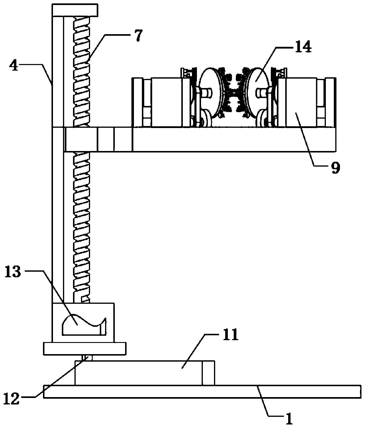
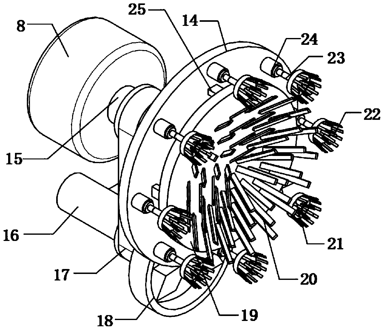
[0028] refer to Figure 1-3 , a cleaning and maintenance device for building construction equipment, comprising a base plate 1 and a slide plate 2, the top outer wall of the slide plate 2 is fixedly connected with a motor box 3, and the inner wall of the motor box 3 is fixedly connected with a No. 2 motor 13, and the output shaft of the No. 2 motor 13 The lead screw 7 is fixed through the coupling, and the top outer wall of the motor box 3 is fixedly connected with the limit groove 4, the top outer wall of the limit groove 4 is fixedly connected with the top plate 6, and the other end of the lead screw 7 is connected to the top plate 6 through a bearing The outer wall of the bottom of the lead screw 7 is threadedly connected with a threaded block 5, the threaded block 5 is slidably connected to the inner wall of the limit groove 4, and the other side outer wall of the threaded block 5 is fixedly connected with a support ring 10, and the support ring 10 is fixedly connected with...

Embodiment 2

[0038] refer to Figure 3-5, a cleaning and maintenance device for building construction equipment, comprising a base plate 1 and a slide plate 2, the top outer wall of the slide plate 2 is fixedly connected with a motor box 3, and the inner wall of the motor box 3 is fixedly connected with a No. 2 motor 13, and the output shaft of the No. 2 motor 13 The lead screw 7 is fixed through the coupling, and the top outer wall of the motor box 3 is fixedly connected with the limit groove 4, the top outer wall of the limit groove 4 is fixedly connected with the top plate 6, and the other end of the lead screw 7 is connected to the top plate 6 through a bearing The outer wall of the bottom of the lead screw 7 is threadedly connected with a threaded block 5, the threaded block 5 is slidably connected to the inner wall of the limit groove 4, and the other side outer wall of the threaded block 5 is fixedly connected with a support ring 10, and the support ring 10 is fixedly connected with ...


PUM


Abstract

The invention belongs to the technical field of construction, and particularly discloses a cleaning and maintaining device for construction equipment. In order to solve the problems that when the equipment is cleaned and maintained through an existing cleaning and maintaining device for construction equipment, due to single-spot sweeping, the working task load is high and omission spots easily occur during sweeping, paid energy is not proportional to harvest and the cleaning and maintaining effect is still poor, now the scheme is put forward. The cleaning and maintaining device comprises a bottom plate and a slide plate. A supporting ring is arranged and is of an elliptical annular structure, cleaning and maintaining apparatuses are installed on the supporting ring, when the equipment is cleaned and maintained, the equipment is cleaned through the cleaning and maintaining apparatuses at all spots on the supporting ring, workload is reduced, and the cleaning effect is improved; and meanwhile, all the apparatuses are slidingly connected to the inner wall of a slide groove through sliders, the position of the cleaning and maintaining device can be adjusted in the equipment cleaning and maintaining process, and therefore it is ensured that there are no dead corners in the cleaning process, and the cleaning and maintaining effect is further improved.

Description

technical field [0001] The invention relates to the technical field of building construction, in particular to a cleaning and maintenance device for building construction equipment. Background technique [0002] Building construction refers to the production activities in the implementation stage of engineering construction. It is the construction process of various buildings. It can also be said to be the process of turning various lines on the design drawings into real objects at designated locations; , the equipment is essential. When the equipment is idle, it needs to be cleaned and maintained to ensure its working effect. [0003] When the existing construction equipment cleaning and maintenance device is used for cleaning and maintenance of equipment, the workload is large through single-point cleaning, and it is easy to miss points during cleaning. After cleaning, dust and other sundries are still attached to the surface. If it is not proportional, the cleaning and m...

Claims


Application Information

Patent Timeline
Patent Type & Authority Applications(China)
IPC IPC(8): B08B1/04B08B13/00B08B15/04F26B21/00
CPCB08B13/00B08B15/04F26B21/004F26B21/001B08B1/12B08B1/32
Inventor 葛飞月
Owner 葛飞月
Learn More