A continuous negative pressure drainage device for orthopedic internal fixation

A technology of internal fixation and negative pressure drainage, which is applied in the medical field, can solve problems such as the impact of normal drainage on the surrounding environment, blockage of the drainage tube, and unfavorable recovery of the patient's wound, so as to achieve continuous usability, large flow space, and not easy to block Effect

Active Publication Date: 2020-12-22
乐清市泰博恒电子科技有限公司
View PDF9 Cites 0 Cited by
  • Summary
  • Abstract
  • Description
  • Claims
  • Application Information

AI Technical Summary

Problems solved by technology

[0002] In the existing medical technology means, pus and blood and other filth will continue to flow out of the patient's wound after the operation. In order to clean up the filth and prevent the patient's wound infection, a negative pressure drainage device was born, but the negative pressure in the prior art The drainage device requires medical staff and patients to always pay attention to whether the drainage bottle is full and needs to be replaced, and the drainage tube is easily blocked by blood clots and other lumps. During thoracic surgery, the patient can squeeze out the blockage by coughing to restore the drainage effect of the drainage device , but the drainage after orthopedic internal fixation and other operations cannot be timely and effectively cleaned up the blockage, the general drainage time is 1-3 days, because the time is long, if the drainage tube is blocked for a long time, and no one finds it Under normal circumstances, it is extremely unfavorable to the recovery of the patient's wound, and if no one finds that the drainage bottle is full, it will also affect the normal drainage and the surrounding environment. Therefore, people need a continuous negative pressure drainage device for orthopedic internal fixation to solve the problem. above question

Method used


Image

  • A continuous negative pressure drainage device for orthopedic internal fixation
  • A continuous negative pressure drainage device for orthopedic internal fixation
  • A continuous negative pressure drainage device for orthopedic internal fixation

Examples


Embodiment

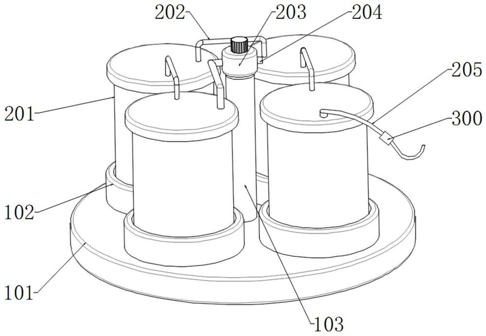
[0023] Example: such as Figure 1-9 As shown, a continuous negative pressure drainage device for orthopedic internal fixation includes a support assembly, a drainage assembly, and a dredging assembly 300. The support assembly is located at the bottom of the device, and the support assembly plays a role in supporting other parts of the device. The support assembly A drainage assembly is arranged above, and the drainage assembly plays the role of draining the filth discharged from the wound. The drainage assembly is provided with a dredging assembly 300, which plays the role of automatically dredging the drainage assembly and preventing internal blockage.

[0024]The support assembly includes a base 101, a fixing base 102, and a mounting column 103. The base 101 is located at the bottom of the whole set of devices. Several fixing bases 102 are fixedly installed above the base 101. A mounting column 103 is fixedly installed in the center of the base 101. The base 101 is placed on ...


PUM


Abstract

The invention discloses a continuous negative pressure drainage device for orthopedic internal fixation, comprising a support assembly, a drainage assembly, and a dredging assembly. The support assembly is located at the bottom of the device, and a drainage assembly is arranged above the support assembly. The drainage component is equipped with a dredging component. The invention is scientific and reasonable, and is safe and convenient to use. The whole process of the device can be carried out without any manual operation. The superimposed and concentrated release of normal negative pressure suction is used to dredge the blockage inside the drainage tube. So that patients do not need to pay attention to observation all the time to avoid the phenomenon of drainage tube blockage, design a large flow check valve main body, ball blocking moving groove, ball blocking, flow channel, instead of using the one-way valve in the prior art to ensure the drainage process The lumps in the valve will not be blocked at the one-way valve. This design is not easy to cause blockage. Several drainage bottles are designed to communicate with each other. When a drainage bottle is full, there is no need to replace the empty drainage bottle immediately, which improves the continuous use of the device. .

Description

technical field [0001] The invention relates to the field of medical technology, in particular to a continuous negative pressure drainage device for orthopedic internal fixation. Background technique [0002] In the existing medical technology means, pus and blood and other filth will continue to flow out of the patient's wound after the operation. In order to clean up the filth and prevent the patient's wound infection, a negative pressure drainage device was born, but the negative pressure in the prior art The drainage device requires medical staff and patients to always pay attention to whether the drainage bottle is full and needs to be replaced, and the drainage tube is easily blocked by blood clots and other lumps. During thoracic surgery, the patient can squeeze out the blockage by coughing to restore the drainage effect of the drainage device , but the drainage after orthopedic internal fixation and other operations cannot be timely and effectively cleaned up the blo...

Claims


Application Information

Patent Timeline
Patent Type & Authority Patents(China)
IPC IPC(8): A61M1/00
CPCA61M1/0023A61M1/0001A61M1/74A61M1/83Y02A50/30
Inventor 王丽燕李祥李育新朱锋锋
Owner 乐清市泰博恒电子科技有限公司
Why Eureka
Try Eureka