
Water level fluctuation type bottom aeration device for water-carrying installation of water body

A technology of water level fluctuation and aeration device, which is used in water aeration, water/sludge/sewage treatment, sustainable biological treatment, etc. problem, to achieve the effect of convenient water detection

Pending Publication Date: 2020-06-23
HUATIAN ENG & TECH CORP MCC
View PDF0 Cites 0 Cited by
  • Summary
  • Abstract
  • Description
  • Claims
  • Application Information

AI Technical Summary

Problems solved by technology

There are still some defects in this design, for example: the traditional bottom aeration system is mostly installed on the bottom of the natural river, the natural river bottom is uneven, the flatness is poor, and the soil quality of the river bottom is unevenly settled, and the installation workload of the microporous aeration system Large, it is difficult to guarantee the installation accuracy, which will easily lead to uneven air output and fail to achieve the expected oxygenation effect
In addition, the natural water body is affected by environmental factors such as climate, and the water level fluctuates greatly. The aeration depth of the bottom aeration head needs to be adjusted accordingly, while the fixed bottom aeration system does not have the adjustment conditions, and the system adaptability is poor
In addition, when the microporous aerator installed at the bottom of the water body is torn or blocked and needs to be repaired, the aerator of the fixed bottom aeration system is fixed underwater, and the water volume of the river is large, and the traditional bottom aeration system drains water. Difficult to maintain

Method used


Image

  • Water level fluctuation type bottom aeration device for water-carrying installation of water body
  • Water level fluctuation type bottom aeration device for water-carrying installation of water body
  • Water level fluctuation type bottom aeration device for water-carrying installation of water body

Examples


Embodiment 1

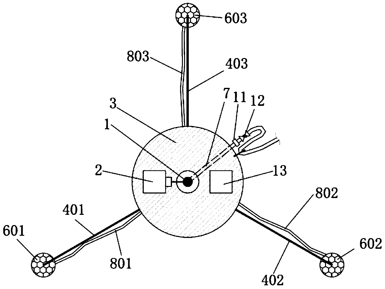
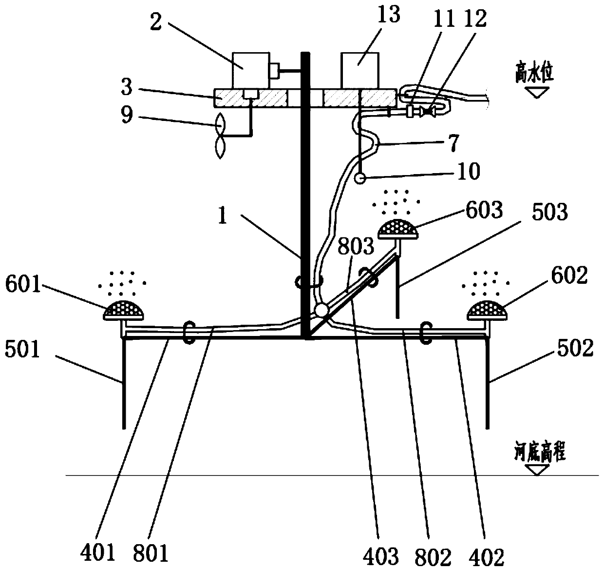
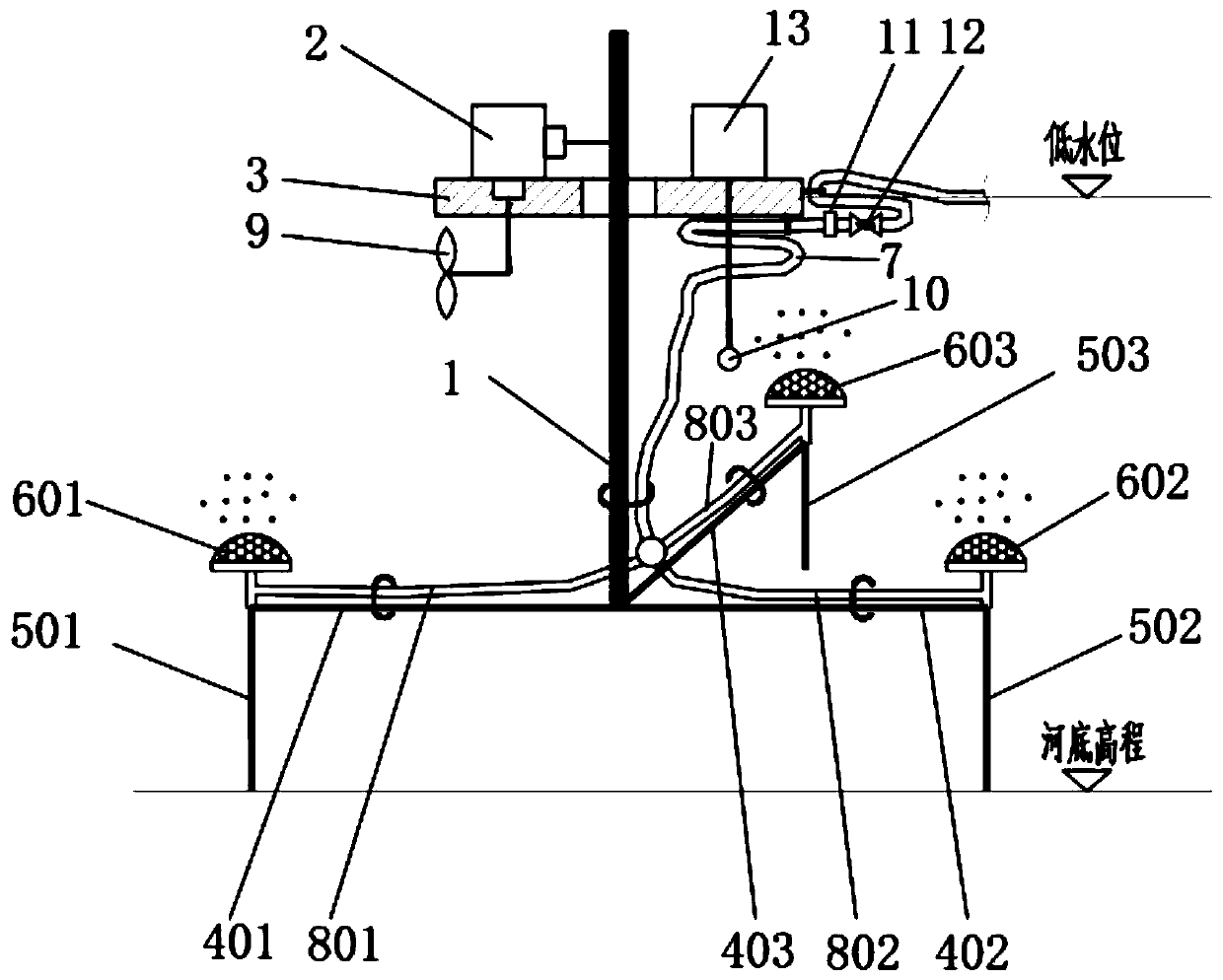
[0020] Embodiment 1 is one of the structures of the present invention. This embodiment includes: a floating body 3, a motor 2 is arranged above the floating body 3, a main rod 1 is arranged in the center of the floating body 3 and passes through the floating body 3, and the main rod 1 and the motor 2 coupling connections. Three crossbars 401, 402, 403 are arranged at the lower end of the main pole 1 and perpendicular to the main pole 1, and the three crossbars 401, 402, 403 are in horizontal positions with equal angles between them. Microporous aeration discs 601, 602, 603 are respectively arranged on the three crossbars 401, 402, 403, and the microporous aeration discs 601, 602, 603 pass through the gas transmission branch hoses 801, 802, 803 on the crossbars 401, 402, 403 and the gas transmission main hoses on the main pole 1 respectively. The gas outlet of the tube 7 is connected. A valve 12 and a union 11 are arranged in sequence near the air inlet on the pipeline from th...

Embodiment 2

[0024] Embodiment 2 is a modification of Embodiment 1. The difference between Embodiment 2 and Embodiment 1 is that a control device 13 is provided above the floating body 3, and a dissolved oxygen probe 10 is disposed below the floating body 3; the dissolved oxygen probe 10 and the motor 2 are respectively connected with the control device 13. A propeller 9 is also arranged under the buoyant body 3 , and the propeller 9 is also connected to the control device 13 .

[0025] In this embodiment, the device drives the motor 2 to run through the control device 13, so as to realize the lifting of the aeration device in the vertical direction; the dissolved oxygen probe 10 is also driven by the control device 13 to monitor the dissolved oxygen content in the river in real time, and the The monitoring data is fed back to the control device 13, and the action of the propeller 9 is controlled by the data fed back: when the monitored dissolved oxygen content in the water body does not r...

Embodiment 3

[0027] Embodiment 3 is a modification of Embodiment 2. The difference between Embodiment 3 and Embodiment 2 is that three support feet 501, 502, 503 are respectively provided below the three cross bars 401, 402, 403, and the three support feet 501, 502, 503 are connected with the three cross bars respectively. 401, 402, 403 are vertical, and three tact switches are respectively arranged on the three support feet 501, 502, 503.

[0028] In this embodiment, support feet 501, 502, 503 are respectively provided under the crossbars 401, 402, 403, so that when the device is at a low water level, the support feet 501, 502, 503 support the entire device to prevent the device from falling to the bottom of the water, resulting in blockage of the microporous aeration trays 601, 602, 603. Since the three support feet 501, 502, and 503 are respectively provided with three tact switches, the tact switches are connected to the control device 13; The device 13 drives the motor 2 to stop runni...


PUM


Abstract

The invention discloses a water level fluctuation type bottom aeration device for water-carrying installation of a water body, and relates to a water body reoxygenation product. The device comprises afloating body, an adjustable aeration bracket and an aerator, an adjustable aeration support is arranged below the floating body, and an aerator is arranged on the adjustable aeration support and connected with the adjustable aeration support through an air conveying hose. Buoyancy is provided for the whole system through the floating body, the aerators are arranged on the adjustable aeration support, the aeration depth of the device can be controlled by adjusting the length of the aeration support, and the device can be checked and replaced under the condition that water is not drained. In addition, a dissolved oxygen probe and a propeller are further arranged, so that the device moves in the horizontal direction, the content of dissolved oxygen in the river body is monitored in real time, and uniform aeration of the device in the river body is ensured.

Description

technical field [0001] The invention relates to a bottom aeration device installed with water in a fluctuating water body. Background technique [0002] The working principle of bottom aeration and oxygen enhancement is that the air is input into the bottom of the water body through the fan and the air pipe, and the air bubbles are released into the water body through the aerator. The bubbles burst during the floating process, and the oxygen is diffused into the water to achieve the oxygenation effect. The improvement of the dissolved oxygen level is beneficial to the oxidation reaction of the water body, accelerates the decomposition of organic matter at the bottom of the pool, and promotes the growth of aquatic animals such as snails that live on the bottom. In the prior art, the microporous aeration system includes an air pipe and a microporous aerator, and the microporous aerator is installed at the bottom of the treated water body to reoxygenate the treated water body. ...

Claims


Application Information

Patent Timeline
Patent Type & Authority Applications(China)
IPC IPC(8): C02F7/00
CPCC02F7/00Y02W10/10
Inventor 吴述园詹茂华程寒飞甘露李旭陈春霄
Owner HUATIAN ENG & TECH CORP MCC
Learn More