A magnetic flat-nose pliers
What is Al technical title?
Al technical title is built by PatSnap Al team. It summarizes the technical point description of the patent document.
A technology of flat-nose pliers and magnetic force, applied in the field of flat-nose pliers, which can solve the problems of inconvenient use of flat-nose pliers, lack of convenient disassembly and assembly functions of magnetic squares, lubrication, etc.
Active Publication Date: 2021-09-21
泗水县特力工具有限公司
View PDF5 Cites 0 Cited by
Summary
Abstract
Description
Claims
Application Information
AI Technical Summary
This helps you quickly interpret patents by identifying the three key elements:
Problems solved by technology
Method used
Benefits of technology
Problems solved by technology
There are certain defects in the currently used flat-nose pliers. The lack of convenient disassembly and assembly of the magnetic square makes it inconvenient to replace and maintain the magnetic square, which reduces the practicability of the flat-nose pliers. At the same time, it lacks a lubrication mechanism, which makes it inconvenient to lubricate the screw rod. Inconvenient to use flat nose pliers
Method used
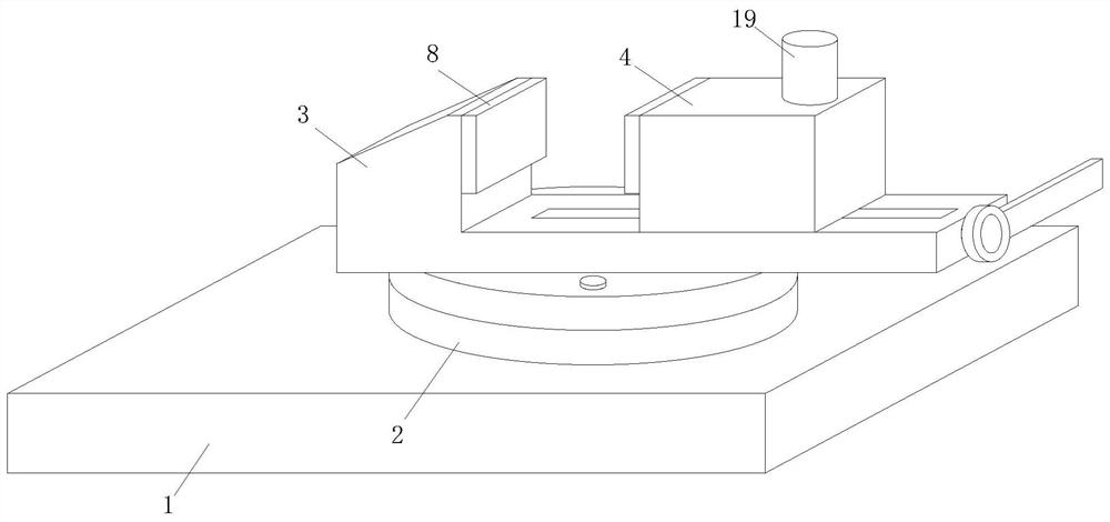
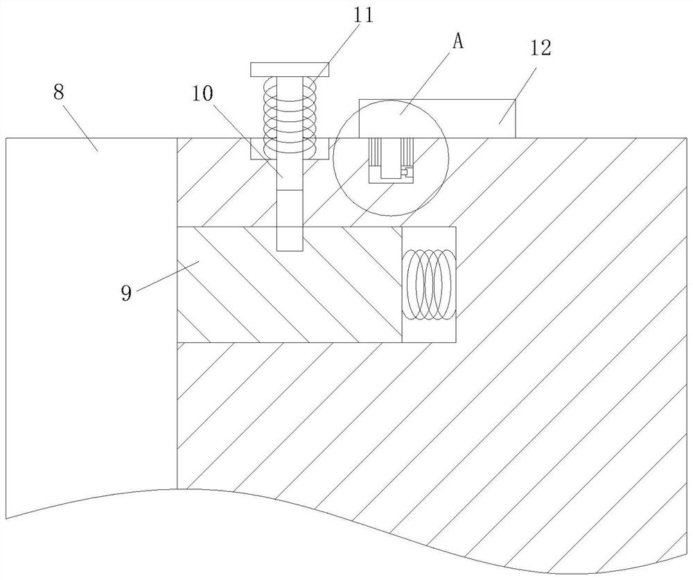
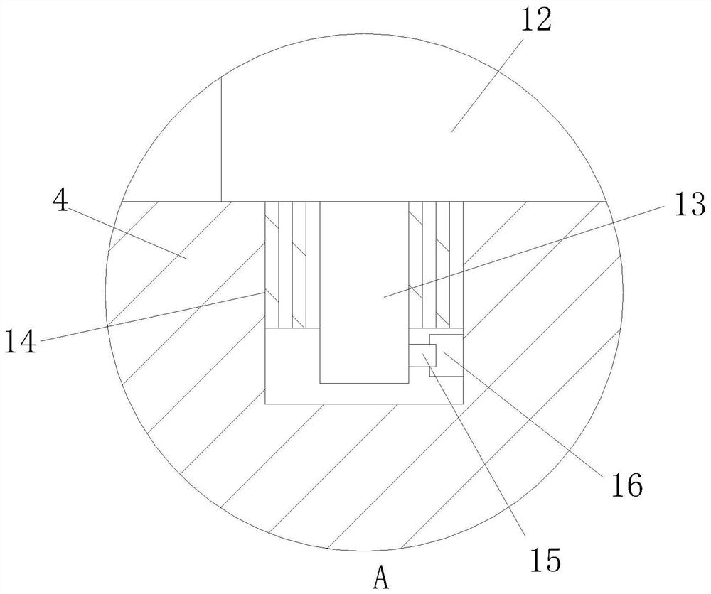
Image
Click on the blue label to locate the original text in one second.
Reading with bidirectional positioning of images and text.
Examples
Embodiment Construction
[0019] In order to make the invention, according to the invention, the invention will be apparent from the accompanying drawings in the embodiment of the present invention, and the technical solutions in the embodiments of the present invention will be clearly described, and it is clear that the following The description described is merely the embodiment of the invention, and not all of the embodiments. Based on the embodiments of the present invention, there are all other embodiments obtained without making creative labor without making creative labor premises.
[0020] The technical solutions of the present invention will be further described below with reference to the accompanying drawings.
[0021] See Figure 1-4 As shown in A magnetic Pliers, comprising a base plate, the rotary disk 2, fixed base 3, the movable block 4, the recess 5, screw 6, the ball nut assembly 7, and a lubricating mechanism mounting means intermediate the base plate 1 to the top position of the mounting...
PUM
Abstract
The present invention relates to the technical field of flat-nose pliers, specifically a magnetic flat-nose pliers, including a base plate, a rotating disc, a fixed seat, a moving seat, a groove, a screw, a ball nut pair, a magnetic square, a mounting rod, a T-shaped rod, Spring one, baffle plate, rotating pin, reset coil spring, magnetic block one, magnetic block two, miniature push rod, pressure plate, oil pot, oil delivery pipe, mounting ring, annular pipe and sponge ring. One end of the T-shaped bar of the present invention moves into the inside of the limiting groove, and then the installation rod is fixedly installed inside the installation groove, and then the user rotates the baffle to separate the first magnetic block from the second magnetic block. Under the action of the elastic force of the reset coil spring, The baffle rotates and fits with the T-shaped rod, and then the T-shaped rod is clamped inside the T-shaped groove. The micro push rod works to drive the pressure plate to move, and the pressure plate moves to squeeze the oil pot, so that the oil inside the oil pot enters the oil delivery pipe. , and then enter the inside of the sponge ring through the oil injection hole, and then apply the oil to the annular side of the screw rod.
Description
Technical field [0001] The present invention relates to a technical field Pliers, specifically a magnetic Pliers. Background technique [0002] Pliers known machine vise, a universal fixture, small parts commonly used in the installation, which is random attachment milling, drilling, and which is fixed to the machine table, for holding a workpiece for cutting. Pliers currently exist certain defects in use, lack of magnetic easy disassembly function Czech, magnetic inconvenient side maintenance replacement, reduces the usefulness of the flat-nose pliers, while the lack of lubrication mechanism, lubrication is inconvenient to the screw, and then flat inconvenient to use of pliers. Accordingly, to provide a magnetic Pliers above problems. Inventive content [0003] Object of the present invention is that to solve the above problems to provide a magnetic Pliers. [0004] The present invention achieves the above object, a magnetic Pliers following technical solutions, including the b...
Claims
Application Information
Patent Timeline
Application Date:The date an application was filed.
Publication Date:The date a patent or application was officially published.
First Publication Date:The earliest publication date of a patent with the same application number.
Issue Date:Publication date of the patent grant document.
PCT Entry Date:The Entry date of PCT National Phase.
Estimated Expiry Date:The statutory expiry date of a patent right according to the Patent Law, and it is the longest term of protection that the patent right can achieve without the termination of the patent right due to other reasons(Term extension factor has been taken into account ).
Invalid Date:Actual expiry date is based on effective date or publication date of legal transaction data of invalid patent.